
Schneider Altivar ATV312 / ATV12 Fault Codes Quick Reference
Table of Contents
This quick reference covers the fault codes technicians encounter most often on ATV312 and ATV12 variable speed drives. It explains what each code means, what to check first, and when the fault is more likely to come from the motor, wiring, load, power supply, or drive itself.
It is not a complete replacement for the programming manual. Always confirm the full drive reference and software version before changing parameters or selecting a replacement.
Safety Before Troubleshooting
Only qualified personnel should work on an Altivar drive system.
Before touching power terminals, motor wiring, or internal components, isolate all power sources, lock out the equipment, wait for the DC bus to discharge as specified in the applicable Schneider Electric manual, and verify the absence of voltage with a properly rated measuring device. A stopped display does not prove that the DC bus is safe.
Do not insulation-test a motor or cable while it is connected to the drive. Disconnect the motor leads from the VFD first and follow the motor and test-equipment manufacturer’s instructions.
- Related Product
Need a Replacement Altivar Drive?
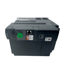
Browse new original Altivar drives for maintenance, troubleshooting, and replacement projects.
- New original parts
- Fast response
- Global shipping
ATV312 and ATV12 Fault Code Quick Reference
| Code | Meaning | Applies to | What to check first |
|---|---|---|---|
OCF | Overcurrent | ATV312 and ATV12 | Mechanical binding, acceleration time, motor data, load current, drive sizing |
SCF | Motor short circuit | ATV312 | Motor cable, motor insulation, output wiring, earth leakage |
SCF1 / SCF3 | Motor/ground short circuit | ATV12 | Output cable, motor insulation, grounding, leakage current |
SCF4 | IGBT short circuit | ATV12 | Internal power-stage fault; isolate motor circuit before judging the drive |
SCF5 | Load short circuit | ATV12 | Output cable and motor insulation, especially when the fault appears at a run command |
SOF | Overspeed | ATV312 and ATV12 | Driven load, speed stability, maximum frequency, braking conditions |
ObF | Overbraking | ATV312 and ATV12 | Deceleration time, regenerative load, line voltage, braking hardware |
OHF | Drive overheat | ATV312 and ATV12 | Cooling path, fan, cabinet temperature, motor load, switching frequency |
OLF | Motor overload | ATV312 and ATV12 | ItH, motor nameplate current, actual motor current, blocked or excessive load |
OPF | Motor phase loss | ATV312 | Motor leads, output contactor, loose terminals, undersized test motor |
OPF1 / OPF2 | One/three output phase loss | ATV12 | Motor connection, output contactor, cable continuity, motor rating |
OSF | Mains overvoltage | ATV312 and ATV12 | Incoming voltage, supply spikes, transformer tap, phase-to-phase voltage |
PHF | Input phase loss | Three-phase variants | Input fuses, phase imbalance, loose supply terminals, correct input phase configuration |
USF | Undervoltage | ATV312 and ATV12 | Incoming voltage under load, contactors, fuses, terminals, voltage dips |
LFF | 4-20 mA loss on AI3 | ATV312 | AI3 loop current, transmitter supply, polarity, terminals, signal assignment |
LFF1 | AI1 current loss | ATV12 | AI1 current configuration, loop current, transmitter supply, CrL1 scaling |
EPF / EPF1 | External fault | ATV312 / ATV12 | External interlock or device assigned to the fault input |
SLF / SLF1 | Modbus communication fault | ATV312 / ATV12 | RS-485 wiring, address, baud rate, parity, timeout, controller state |
CFF / CFI | Incorrect or invalid configuration | Both families | Recent parameter download, HMI replacement, option change, valid backup file |
CrF / CrF1 | Precharge fault | ATV312 / ATV12 | Supply stability and internal precharge circuit; persistent faults require escalation |
tnF | Auto-tuning fault | ATV312 and ATV12 | Motor connection, motor compatibility, output contactor, motor rotation during tuning |
The code names above are drawn from Schneider Electric’s ATV312 Programming Manual BBV46385 and ATV12 User Manual BBV28581. The tables in those manuals also separate faults by reset behavior, which matters when deciding whether a keypad reset, logic input, automatic restart, or power cycle is permitted.
OCF: Overcurrent
OCF means the drive detected excessive output current. On both families, Schneider lists incorrect motor-control settings, excessive inertia or load, and mechanical locking among the main causes.
Start with the machine, not the keypad. Confirm that the shaft, gearbox, pump, conveyor, or fan can move normally. An aggressive acceleration ramp can produce OCF even when the machine runs correctly at constant speed.
Then compare the motor nameplate with the drive settings. Check the rated motor voltage, rated motor current, rated speed, base frequency, motor control type, and motor thermal current setting ItH. Monitor motor current while the machine runs and compare it with the motor full-load current.
If OCF occurs only during acceleration, increase the acceleration time as a diagnostic test and check whether the driven load has changed. If it appears at constant speed, look more closely at process load, mechanical drag, low supply voltage, and drive/motor sizing.
Do not keep increasing current limits to make the fault disappear. That can hide a mechanical problem and remove useful protection.
SCF, SCF1, SCF3, SCF4, and SCF5: Short-Circuit Faults
These codes should be treated more seriously than a normal overload.
On the ATV312, SCF indicates a short circuit or grounding condition at the drive output. On the ATV12, Schneider separates the diagnosis into more detailed codes: SCF1 for a motor or ground short circuit, SCF3 for a ground short circuit, SCF4 for an IGBT short circuit, and SCF5 for a load short circuit detected under defined test or start conditions.
After safe isolation, inspect the complete path from the drive’s U/T1, V/T2, and W/T3 terminals to the motor. Look for crushed cable, moisture, carbon tracking, loose strands, damaged junction boxes, and contactors that are opening or closing while the drive is producing output.
Disconnect the motor leads from the drive before carrying out continuity or insulation tests. Test the cable and motor separately. If the fault remains when the motor circuit has been proven healthy, the power stage may be damaged, particularly when the code is SCF4 or the fault appears immediately at power-up.
- PLC Solutions
Find the Right PLC for Your System
Explore new original PLC CPUs, I/O modules, power supplies, and communication units for maintenance and automation projects.
- New original parts
- Fast response
- Global shipping
SOF: Overspeed
SOF indicates that the estimated motor speed has exceeded the permitted level. Schneider associates it with instability or a load that drives the motor faster than commanded.
On the ATV12, the manual defines the overspeed point in relation to maximum frequency tFr, so an incorrectly low tFr setting can contribute to the trip. Check the commanded frequency, tFr, motor parameters, and speed-loop stability settings before increasing any limit.
If SOF appears during deceleration, the load may be regenerating into the drive. High-inertia fans, centrifuges, unwinders, and descending loads can continue to drive the motor as the VFD reduces its output frequency. A longer deceleration time or correctly selected braking hardware may be required.
ObF and OSF: Do Not Confuse Braking With Supply Overvoltage
ObF is an overbraking fault. It usually appears while the motor is decelerating and returning energy to the DC bus. Increase the deceleration time first. Check whether the load is overhauling, whether the line voltage is already high, and whether the application requires an approved braking module or resistor.
OSF is a mains overvoltage fault. Check the actual input voltage at the drive, compare it with the rating on the nameplate, and look for supply disturbances or incorrect transformer taps.
The timing is useful evidence. An overvoltage code while stopped or at power-up points more strongly toward the supply. A trip during rapid deceleration points more strongly toward regenerated braking energy.
OHF and OLF: Drive Heat Versus Motor Heat
OHF means the drive temperature is too high. Check the cabinet ambient temperature, ventilation openings, heatsink contamination, fan operation where fitted, mounting clearance, switching frequency, and load. Wait for the drive to cool before restarting.
OLF is a calculated motor overload fault. It is normally associated with motor current remaining above the thermal protection setting for long enough to reach the trip threshold. Confirm that ItH matches the motor nameplate current and that the actual current is balanced and appropriate for the load.
Resetting OLF without correcting the load or thermal setting does not solve the problem. Also remember that external motor thermal protection may be required for multiple motors, very small motors, motor switching, or applications where the drive’s model does not retain thermal state after power loss.
OPF, OPF1, OPF2, and PHF: Phase-Loss Faults
OPF on the ATV312 and OPF1/OPF2 on the ATV12 concern the drive-to-motor side. Check all three motor leads, output terminals, cable continuity, motor windings, and any downstream contactor. An output contactor must not open while the drive is supplying the motor unless the control system and drive configuration are designed for it.
PHF concerns the incoming supply on applicable three-phase models. Check all input fuses, phase-to-phase voltages, terminal tightness, contactor condition, and phase balance. The protection is load-dependent, so a weak phase can appear normal with the drive idle and collapse when current rises.
Do not disable phase-loss detection simply to keep a machine running. Schneider provides configuration options for specific test or supply arrangements, but those settings should only be changed after confirming that the exact drive and application permit it.
USF: Undervoltage
USF means the line supply or DC bus has fallen below the drive’s threshold. Measure the input voltage while the fault is occurring, not only when the machine is idle.
Common causes include a weak supply, undersized wiring, a failing upstream contactor, loose terminals, blown or high-resistance fuses, generator instability, and voltage sag when another large load starts. If the voltage at the drive remains correct during the event, the internal precharge or measurement circuit may require further investigation.
LFF, LFF1, EPF, and EPF1: External Signal Faults
The ATV312 uses LFF for loss of the 4-20 mA reference on AI3. The ATV12 uses LFF1 for an AI1 current-loss condition when AI1 is configured for current and the scaling conditions in the manual are met.
Measure the loop current, verify transmitter power, check polarity and common connections, and confirm the analog input assignment. Do not bypass the loss-of-signal response until you have considered what the machine should do when the sensor cable breaks.
EPF on the ATV312 and EPF1 on the ATV12 are user-defined external faults. The VFD is reporting an event from an assigned logic input or control function. Trace the external circuit: safety relay status, pressure switch, thermal contact, PLC output, permissive relay, or other interlock.
This is a common point where unnecessary drive replacement happens. If the external input is active, replacing the VFD will not remove the real cause.
- HMI Replacement
Upgrade or Replace Your HMI
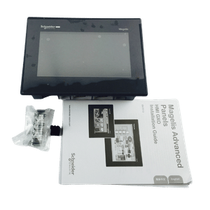
Find compatible HMI panels for discontinued models, machine upgrades, and operator interface replacement.
- New original parts
- Fast response
- Global shipping
SLF and Other Communication Faults
For Modbus faults, inspect the communication system as a network rather than changing motor parameters. Check RS-485 polarity, shielding and grounding practice, termination where applicable, node address, baud rate, parity, timeout values, controller state, and cable routing near power conductors.
The ATV312 may also report COF for CANopen interruption or CnF for a communication option-card fault. The ATV12 divides communication-related events into codes such as SLF1, SLF2, and SLF3 for Modbus, SoMove, and remote HMI communication.
Record whether the fault occurs at power-up, when the PLC changes mode, or only when a nearby contactor or motor starts. That timing helps separate configuration and timeout problems from electromagnetic interference.
CFF and CFI: Configuration Faults
CFF indicates an inconsistent configuration. CFI indicates that a configuration transferred through a communication link is invalid or incompatible.
These faults often follow an HMI block change, option change, interrupted download, or parameter file copied from a different drive rating. Use a verified backup from the same model and application. A factory reset may clear an inconsistent configuration, but it also removes application settings, so document or back up the existing parameters first whenever possible.
Codes That Are Status Messages, Not Faults
Several normal operating states are often mistaken for alarms:
rdY: drive readynSt: freewheel stop activeFSt: fast stop activedCb: DC injection braking in progresstUn: auto-tuning in progressInIt: initialization in progress
If the display shows nSt, check the stop-input logic, two-wire or three-wire control selection, active freewheel-stop assignment, local STOP command, and communication control state. It is usually telling you why the drive is not permitted to run, not reporting a failed power stage.
How to Reset an ATV312 or ATV12 Fault Safely
There is no single reset method for every code.
First remove the cause. Then check the manual’s reset category for that code. Depending on the model and configuration, a fault may clear when its cause disappears, through the STOP/RESET key, through an assigned fault-reset logic input rSF, through automatic restart, or only after a power cycle.
Automatic restart should only be enabled when an unexpected restart cannot create a hazard. Never use repeated power cycles as a troubleshooting method for SCF, internal, or precharge faults.
A sensible reset sequence is:
- Record the displayed code and the operating condition.
- Remove the run command and make the machine safe.
- Inspect and correct the likely external cause.
- Use only a reset method permitted for that fault and application.
- Run the machine at low risk while monitoring current, voltage, and load.
- Stop testing if the same fault returns.
A Practical Diagnostic Order
When the machine is down, use this order to avoid replacing good hardware:
- Record the full drive reference, fault code, recent fault history, and when the trip occurs.
- Check the supply voltage, fuses, contactors, and terminal condition.
- Check the motor, cable, grounding, insulation, and mechanical load.
- Compare motor nameplate data with drive parameters.
- Review acceleration, deceleration, current, thermal, braking, and communication settings.
- Test external interlocks and analog signals.
- Reset once after correcting the cause and observe the machine under controlled conditions.
- Escalate persistent internal, precharge, or power-stage faults for replacement evaluation.
Frequently Asked Questions
No. The two families share several codes, including OCF, SOF, ObF, OHF, OLF, OSF, and USF, but the ATV12 uses more detailed variants such as SCF1, SCF3, SCF4, SCF5, OPF1, OPF2, LFF1, and EPF1. Always use the manual for the exact drive family and software version.
No. nSt is a freewheel-stop status. Check the stop-input state, two-wire or three-wire control logic, any assigned freewheel-stop input, the keypad STOP command, and the network control sequence.
Remove the cause before resetting. For OCF, check mechanical load and motor settings; for SCF, isolate power and test the motor cable and motor separately from the drive. The permitted reset method depends on the exact model and code category, and a recurring short-circuit fault should not be repeatedly reset.
ObF normally points to excessive regenerative energy during braking, while OSF points to excessive mains voltage. A trip during fast deceleration suggests checking the ramp and load inertia; a trip at power-up or while stopped suggests checking the incoming supply.
The ATV320 is Schneider Electric’s designated successor to the ATV312, but the conversion still requires a model and application review. An ATV12 of the same kW is not automatically equivalent because I/O, communication, control functions, overload capability, braking, dimensions, and parameters may differ.
Power your projects with brand-new, original Omron, Mitsubishi, Schneider Servo – in stock, ready now!
Replacing an ATV312 or ATV12 Drive
Schneider Electric identifies the ATV320 family as the current replacement line for the obsolete ATV312. The ATV320 has similar capabilities, but it is not a parameter-for-parameter or wiring-for-wiring substitute. Control architecture, front-panel operation, communication options, safety functions, dimensions, and parameter migration all need to be checked.
An ATV12 is not a universal substitute for an ATV312 simply because the power rating matches. Select a replacement by complete catalog number, input voltage and phase, rated output current, overload duty, motor type, braking requirement, control method, I/O, communication, enclosure, ambient conditions, and physical size.
For a Kwoco replacement check, send the full drive model, motor nameplate photo, cabinet photo, fault code, control wiring details, and an available parameter backup. That information is much more useful than motor kW alone and helps avoid ordering a drive that cannot reproduce the original machine functions.
Contact Us
Just fill out your name, email address, and a brief description of your inquiry in this form. We will contact you within 24 hours.
Product Category
Hot Sale Products
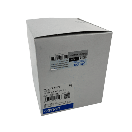
Omron CPU Unit CJ2M-CPU32
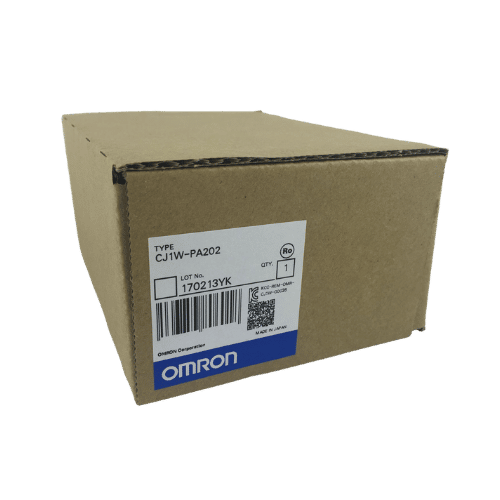
Omron PLC CJ1W-PA202 Supplier in China
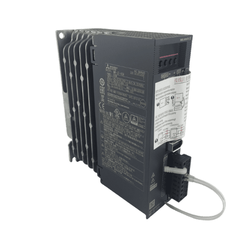
Mitsubishi MR-JE Series 400w Servo Drive MR-JE-40A
Need a Fast Match?
Share your model or spec and our team will help you find the right fit-fast.
- Expert support
- Quick response
- Competitive price
- +86-755-81481609
- [email protected]
You May Also Find These Topics Interesting
Choosing the Right Terminal Block: A Complete Guide
Terminal blocks are essential components in electrical systems, ensuring organized and secure connections between multiple wires. These devices come in a variety
How to Choose an Omron EtherCAT HMI and Motion Stack
Omron’s EtherCAT-based machine control ecosystem is attractive to modern builders because it is designed to connect motion, I/O, sensing, and related automation
Why Your Business Needs a Variable Frequency Drive
Why Your Business Needs a Variable Frequency Drive When managing industrial operations, optimizing energy efficiency while maintaining performance is crucial. However, achieving