
Omron R88D Servo Drive Alarm Codes Explained
Table of Contents
That detail matters because R88D is a product prefix, not one servo-drive family. An R88D-KT G5 pulse-input drive, an R88D-KN G5 EtherCAT drive, and an R88D-1SN 1S EtherCAT drive do not use one universal alarm table. Some main codes overlap, but subcodes, reset conditions, network diagnostics, and encoder systems can differ.
This guide covers the current 1S family and the widely installed G5 family. It explains the codes technicians see most often, what usually causes them, and the checks that should be completed before resetting the drive.
Identify the R88D Series First
Read the full model from the drive nameplate before changing wiring or parameters.
| Drive model prefix | Omron family | Control interface | Main manual |
|---|---|---|---|
| R88D-KT | G5 | General-purpose pulse train or analog input | I571 |
| R88D-KN…-ML2 | G5 | MECHATROLINK-II | I572 |
| R88D-KN…-ECT | G5 | EtherCAT | I576 |
| R88D-1SN…-ECT | 1S | EtherCAT | I586 |
| R88D-1SAN… | 1S with safety functions | EtherCAT and safety functions | Manual for the exact safety model |
Older R88D-W, R88D-GT, R88D-GN, and other discontinued families have their own alarm lists. Do not use a G5 parameter number or 1S reset procedure on an older drive simply because the alarm number looks familiar.
Safety Before Troubleshooting
A servo drive can retain hazardous DC voltage after incoming power is removed. A dark seven-segment display is not proof that the main circuit is discharged.
Before touching the power terminals, motor wiring, regeneration resistor, or connectors:
- Stop the machine and remove the Servo ON or RUN command.
- Isolate the main and control power supplies according to the machine’s lockout procedure.
- Wait for the charge indicator to turn off.
- Observe the waiting time specified for the exact drive model. Omron specifies model-dependent waiting periods of 10, 15, or 20 minutes for 1S drives.
- Confirm with a suitable meter that hazardous voltage is no longer present.
Do not disconnect or reconnect U, V, W, encoder, brake, or regeneration wiring while the drive is energized. Insulation testing should be performed only by qualified personnel, with the motor and cable disconnected from the servo drive as required by the manual.
- Related Product
Need a Replacement Servo Drive?
Browse new original Servo drives for maintenance, troubleshooting, and replacement projects.
- New original parts
- Fast response
- Global shipping
How Omron R88D Alarm Numbers Are Displayed
G5 alarm format
G5 manuals normally write an alarm as a main code and subcode, such as:
- 14.0 – overcurrent
- 16.0 – overload
- 21.1 – encoder communications error
The drive stores the current alarm and up to 13 previous alarms. That history is often more valuable than the current display. For example, repeated undervoltage alarms immediately before an overcurrent alarm point toward a supply or contactor problem rather than three unrelated failures.
Some G5 alarms are not stored in alarm history, including control-power undervoltage, certain parameter errors, drive-prohibition input errors, and motor non-conformity. If the fault is intermittent, record the display before cycling power.
1S alarm format
The 1S drive displays Er, followed by a hexadecimal main code and subcode. For example, Er 16 00 is Overload Error and Er 83 03 is Communications Synchronization Error.
Sysmac Studio provides the error name, history, related objects, and network information. Record both bytes. 13.00 and 13.01, for example, identify different supply problems.
Omron R88D Common Alarm Codes Quick Reference
The table below focuses on codes that are common in field service. Always confirm the exact definition in the manual for the drive model.
| Alarm | Typical meaning | Applies to | First checks |
|---|---|---|---|
| 11.0 | Control power supply undervoltage | G5 | L1C/L2C voltage, control supply capacity, loose terminals |
| 12.0 | DC bus overvoltage | G5 and 1S | Incoming voltage, deceleration profile, regeneration circuit |
| 13.0 | Main power supply undervoltage | G5 and 1S | Mains voltage, contactor, fuse, cable, supply capacity |
| 13.1 / 13.01 | AC cutoff or main-circuit phase loss, depending on series | G5 / 1S | Exact manual, phase wiring, supply dips, phase-loss settings |
| 14.0 | Overcurrent | G5 and 1S | U/V/W short, ground fault, motor cable, motor winding, drive power stage |
| 14.1 / 14.01 | IPM or power-module error | G5 and 1S | Motor circuit, regeneration wiring, power module |
| 15.0 | Servo drive overheat | G5 and 1S | Cabinet temperature, fan, airflow, sustained load |
| 15.01 | Motor overheat | 1S | Motor ambient temperature, load ratio, motor condition |
| 16.0 / 16.00 | Overload | G5 and 1S | Mechanical load, brake release, acceleration, tuning, sizing |
| 18.0 / 18.00 | Regeneration overload | G5 and 1S | Deceleration energy, vertical load, resistor selection and settings |
| 18.1 / 18.01 | Regeneration circuit error | G5 and 1S | Resistor wiring and value, short circuit, drive circuit |
| 21.0 / 21.00 | Encoder communications disconnected | G5 and 1S | Encoder plugs, cable continuity, shielding, cable routing |
| 21.1 / 21.01 | Encoder communications error | G5 and 1S | Noise, shield/FG, connector contact, recommended cable |
| 23.0 | Encoder communications data error | G5 | Encoder cable, supply voltage, electrical noise |
| 24.0 / 24.00 | Excessive position deviation | G5 and 1S | Jam, torque saturation, brake, gains, acceleration time |
| 24.1 / 24.01 | Excessive speed deviation | G5 and 1S | Load restriction, tuning, speed-deviation setting |
| 26.0 / 26.00 | Excessive speed | G5 and 1S | Speed command, electronic gear, overshoot, external force |
| 30.0 | Safety input error or ST status | G5 | Safety input circuit and machine safety logic |
| 34.0 / 34.01 | Overrun or software limit exceeded | G5 / 1S | Limit inputs, software limits, commanded position |
| 36.0 / 36.00 | Parameter or non-volatile data error | G5 and 1S | Parameter file, write interruption, drive memory |
| 37.0 / 37.00 | Parameter destruction or memory hardware error | G5 and 1S | Reload verified data; replace drive if persistent |
| 38.0 / 38.00 | Drive prohibition input error | G5 and 1S | Positive/negative limit inputs and input logic |
| 40.0 | Absolute encoder system down or low battery supply | G5 | Encoder battery, cable, absolute encoder initialization |
| 83.xx | EtherCAT state or synchronization error | 1S | Master event log, cycle setting, node state, network stability |
| 87.0 / 87.00 | Error-stop input active | G5 and 1S | Emergency-stop chain and assigned input |
| 90.xx | EtherCAT configuration error | 1S | PDO mapping, distributed clock, Sync Manager, watchdog settings |
| 95.x | Motor non-conformity | G5 and 1S | Drive-motor combination, capacity, voltage, encoder |
| 99.99 | Misalignment alert | 1S | Encoder communications history and prescribed reset procedure |
Two cautions are worth repeating.
First, a shared main code does not guarantee an identical subcode. On G5, 13.1 is associated with an AC supply interruption. On 1S, 13.01 is Main Circuit Power Supply Phase Loss Error.
Second, the 1S uses a batteryless absolute encoder. The G5 40.0 battery-related remedy should not be applied to a 1S drive.
Alarm 11.0 and 13.x: Power Supply Undervoltage
11.0 is a G5 control-power undervoltage alarm. Check the voltage at L1C and L2C while the machine is attempting to start, not only when it is idle. A supply that reads correctly with no load can collapse during inrush.
13.0 means the main DC bus fell below its operating range during Servo ON. Common causes include:
- Low incoming voltage
- A momentary power dip
- An undersized transformer or power supply
- A worn contactor or loose terminal
- A blown fuse or missing phase
- Incorrect single-phase or three-phase wiring
On a 1S drive, 13.01 specifically indicates main-circuit phase loss. Check whether the drive is a three-phase-only model or a model that permits single-phase input. If single-phase operation is permitted, confirm the phase-loss detection setting against the manual rather than disabling protection as a guess.
Measure all phases under operating conditions. If several drives alarm together, investigate the upstream supply before replacing an individual servo drive.
- Servo Solutions
Find the Right Sero for Your System
Explore new original servo motor for maintenance and automation projects.
- New original parts
- Fast response
- Global shipping
Alarm 12.0: Overvoltage
Overvoltage is usually produced by one of two conditions: the incoming supply is too high, or the motor is returning more energy to the DC bus than the drive can process.
Start with the incoming voltage. Check for an incorrect transformer tap, unstable generator or UPS output, and power-factor correction equipment on the same supply.
Then inspect the regeneration circuit. Verify the B1/B2 wiring, resistor continuity, resistance value, power rating, and related parameter settings. An open resistor can turn a normal deceleration into an overvoltage trip.
If the alarm appears only during deceleration, increase the deceleration time and review the load inertia. On a vertical axis, lowering a heavy load can be regenerative even at a moderate speed.
Do not install a lower-resistance resistor simply to make the alarm disappear. A value below the drive’s permitted resistance can damage the regeneration transistor.
Alarm 14.x: Overcurrent and Power-Module Faults
An overcurrent alarm means current exceeded the protection level. It is more urgent than an ordinary overload alarm.
Before blaming the drive, isolate the equipment and inspect:
- U, V, and W for phase-to-phase shorts
- Each motor phase for a fault to ground
- Motor-cable connectors for bent pins, contamination, or poor contact
- Cable damage at moving carriers and flex points
- Motor windings for abnormal resistance imbalance
- External regeneration wiring for a short circuit
For qualified testing, disconnect the motor cable from the drive before checking cable or motor insulation. Never apply a megohmmeter to the servo drive output terminals.
If 14.0 returns immediately with the motor circuit safely disconnected and the external wiring has been ruled out, the drive power stage becomes a strong suspect. Follow the model manual’s test procedure or replace the drive.
Do not keep resetting an overcurrent alarm. Repeated energization can turn a repairable cable or motor fault into a failed power module.
Alarm 15.x and 16.0: Overheat Versus Overload
15.0 reports excessive drive temperature. Check cabinet filters, fans, spacing, ambient temperature, and whether another heat source is exhausting directly onto the drive.
The 1S 15.01 is a motor overheat error detected through the encoder system. Check the actual motor environment and load before treating it as an encoder fault.
16.0 is an electronic thermal overload. Frequent causes are:
- A seized bearing, binding ball screw, or damaged gearbox
- An electromagnetic brake that has not released
- Excessive acceleration or deceleration
- Long operation near or above rated torque
- Incorrect inertia-ratio or gain settings causing hunting
- Wrong motor and encoder cables connected across adjacent axes
- A motor or drive that is too small for the duty cycle
Use CX-Drive for G5 or Sysmac Studio for 1S to inspect torque, speed, position deviation, and load ratio. A high average torque points toward load or sizing. Rapid positive-negative torque oscillation points more toward tuning, looseness, or mechanical resonance.
Increasing a torque limit or alarm threshold without understanding the load is not a repair. It can move the failure from the drive display to the motor, coupling, or machine.
Alarm 18.x: Regeneration Overload
Regeneration overload means the resistor’s calculated or monitored load exceeded its allowable level. The resistor may be healthy.
Look at the motion profile first. High inertia, short deceleration, repeated indexing, and descending vertical loads all increase regenerative energy. Lengthening deceleration or reducing speed is often the quickest diagnostic test.
If an external resistor is installed, confirm:
- The approved resistance range for the exact drive
- The resistor’s continuous and short-time power rating
- Correct terminals and sound connections
- Matching regeneration parameters
- Required thermal protection
Omron states that the regeneration resistor is not intended for continuous regenerative braking. A continuously overhauling load requires a system design that can handle continuous returned energy, not repeated alarm resets.
Alarm 21.x and 23.0: Encoder Communication
Encoder alarms are often caused by the cable or installation environment, not the encoder itself.
Inspect both connectors for full engagement and damaged contacts. Check the cable at drag-chain exits, motor junctions, and cabinet entry points. Keep the encoder cable separate from U/V/W motor cables and braking-resistor wiring. Connect the shield and protective earth as specified by Omron.
On G5 systems, verify the encoder supply at the encoder end where the manual calls for it. Long or non-approved cables can create voltage drop even when the supply looks correct at the drive.
If the alarm appears only when another motor, contactor, or heater switches, capture the timing and improve grounding, shielding, cable separation, and surge suppression. Replacing the encoder will not fix conducted or radiated noise.
After cable checks, exchange parts only in a controlled way. A known-good approved encoder cable is a better first substitution than a new motor.
Alarm 24.x, 26.0, and 34.x: The Axis Is Not Where It Should Be
24.0 means the motor position did not follow the command within the permitted following-error window. It does not automatically mean the encoder is defective.
Check whether the axis is physically blocked, the brake is released, and the commanded acceleration is realistic. Monitor torque. If torque is saturated while position error grows, the servo is trying to move but cannot generate enough effective torque.
24.1 concerns excessive speed deviation. Review tuning, load restriction, and the configured detection level.
26.0 means actual speed reached or exceeded the excessive-speed setting. Check the command value, electronic gear ratio, overshoot, encoder feedback, and whether an external load is driving the motor.
For travel-limit alarms, identify the family:
- G5 34.0 concerns the overrun limit range.
- 1S 34.01 means the actual position exceeded the configured software position limit.
Do not bypass a hardware or software limit to clear production. Jog the axis only under a controlled recovery procedure that keeps people and tooling out of the travel path.
Safety and Stop-Input Codes
On G5, 30.0 is associated with the safety inputs and may appear as ST. On 1S, C0.00 is STO Detected information; it can be changed to an error through information customization.
38.0 indicates a drive-prohibition input problem. On G5 this commonly means both forward and reverse prohibition inputs are inactive. Check the input assignments, normally open/normally closed logic, field wiring, and actual machine limit switches.
87.0 or 87.00 means the assigned error-stop input is active.
These inputs are part of the machine’s protective design. Do not jumper STO, emergency-stop, or travel-limit circuits as a troubleshooting shortcut. Verify the circuit against the electrical drawing and safety design.
- HMI Replacement
Upgrade or Replace Your HMI
Find compatible HMI panels for discontinued models, machine upgrades, and operator interface replacement.
- New original parts
- Fast response
- Global shipping
Parameter, Memory, and Motor-Matching Errors
For G5, 36.x indicates a parameter read or data problem and 37.x indicates parameter-data destruction. On 1S, 36.00 is Non-volatile Memory Data Error and 37.00 is Non-volatile Memory Hardware Error.
Reload only a verified parameter file for the same machine axis and exact hardware. If the memory error returns after the approved initialization or power-cycle procedure, replace the drive.
95.x means the connected motor does not conform to what the drive expects. Compare the complete motor and drive model numbers, not only their kilowatt ratings. Voltage class, rated capacity, encoder type, brake option, and supported combination all matter.
For 1S 99.99, a normal reset is intentionally insufficient. Omron requires the encoder Communications Error Count to be cleared in Sysmac Studio before performing the regular reset. Because the warning indicates possible absolute-position misalignment, verify the machine reference before automatic operation.
1S EtherCAT Errors: 83.xx and 90.xx
On an R88D-1SN drive, an EtherCAT problem may be a network error rather than a motor or power-stage fault.
The 83.xx group includes EtherCAT state-change, illegal state-change, synchronization, communications-synchronization, and Sync Manager watchdog errors.
The 90.xx group covers configuration problems such as mailbox settings, PDO watchdogs, Sync Manager event mode, distributed clocks, synchronization cycle, and RxPDO/TxPDO mapping.
Check the controller event log and the drive’s exact subcode before touching the motor. Confirm:
- Node address and expected network position
- EtherCAT IN and OUT cable orientation
- Link and error indicators
- Approved shielded industrial Ethernet cable
- Distributed-clock and synchronization-cycle settings
- PDO mapping against the current ESI file and project
- Whether the error began after a controller, project, drive, or firmware change
If the network reaches Operational state and then drops only when the machine moves, inspect cable routing, connector strain, shielding, and noise from the motor circuit. If it never reaches the requested state after a project change, start with configuration rather than hardware.
How to Reset an Omron R88D Alarm Safely
Use this sequence:
- Record the complete drive model, main code, subcode, operating step, and alarm history.
- Remove Servo ON or RUN and make sure no motion command remains active.
- Correct the actual cause.
- Use the permitted reset method for that alarm and model.
- If the manual marks the error as power-cycle-only, isolate and restore power through the machine’s normal procedure.
- Re-enable the axis at low speed and reduced risk, then monitor current, torque, temperature, position deviation, and regeneration load.
G5 alarms can be reset through the assigned RESET input, a power cycle, or CX-Drive when the alarm permits it. The 1S supports power cycling, an EtherCAT error-reset command, or Sysmac Studio. Some 1S errors require power cycling or Unit Restart instead of an ordinary reset.
Never reset with RUN still active. Omron warns that the motor may start immediately when the alarm clears.
A Practical Troubleshooting Order
When downtime is expensive, a fixed sequence prevents random part swapping:
- Capture evidence. Photograph the display and nameplate. Save the alarm history and controller event log.
- Classify the fault. Supply, power stage, thermal/load, regeneration, feedback, motion deviation, safety input, parameters, or network.
- Check what changed. Recent motor replacement, parameter download, cable work, mechanical service, controller project, or power event.
- Inspect before measuring. Loose plugs, burned terminals, blocked fans, damaged drag-chain cable, brake wiring, and jammed mechanics are common.
- Measure the relevant circuit. Supply voltage for 13.x, insulation and phase balance for 14.x, torque for 16.0, and regeneration load for 18.0.
- Change one variable at a time. A known-good cable or controlled longer deceleration gives more information than replacing several components together.
- Verify under the original duty cycle. One successful low-speed jog does not prove that an intermittent overload or regeneration problem is gone.
Frequently Asked Questions
Yes, but only if the exact alarm is marked as resettable. G5 may accept the RESET input or CX-Drive, while 1S may accept an EtherCAT reset command or Sysmac Studio. Power-module, memory, and certain encoder errors require a power cycle or Unit Restart. Remove the cause and turn off RUN or Servo ON before resetting.
Alarm 14 is overcurrent: current exceeded the drive’s protection level, often because of a short, ground fault, cable problem, or failed power stage. Alarm 16 is electronic thermal overload, more commonly associated with excessive mechanical load, a brake that remains applied, aggressive acceleration, poor tuning, or undersized equipment.
The cable may not be the root cause. Check connector engagement, shield and FG termination, separation from motor cables, motor grounding, approved cable type, and encoder supply conditions. If the alarm is synchronized with contactor or motor switching, electrical noise is a stronger suspect.
Not necessarily. Alarm 18 often means the motion cycle is producing more regenerative energy than the selected resistor and drive can handle. Check deceleration time, load inertia, vertical-axis behavior, resistor settings, resistance, wiring, and monitored regeneration load before replacing the resistor.
No, it should be treated as a planned migration, not a drop-in substitution. Omron’s I868 replacement guide requires checks for the matching drive and motor, mounting dimensions, connectors, cables, EtherCAT objects, parameters, and controller project. Preserve the original parameter backup and verify every axis-specific function.
Power your projects with brand-new, original Omron, Mitsubishi, Schneider Servo – in stock, ready now!
When Replacement Is the Sensible Fix
Replacement becomes reasonable when a power-module or non-volatile-memory fault remains after external circuits have been checked, when the drive is physically damaged, or when an older unit can no longer be supported economically.
For a reliable match, collect:
- Complete R88D drive model
- Complete R88M motor model
- Supply voltage and phase
- Control interface
- Motor power and encoder cable models
- Brake and absolute-encoder details
- Parameter backup and machine application
Kwoco can help verify these details when sourcing an Omron servo drive, motor, cable, or replacement set. Sending clear nameplate photos from both the drive and motor is usually faster and safer than selecting from power rating alone, especially for a G5-to-1S migration.
Omron publishes a dedicated G5 EtherCAT to 1S EtherCAT replacement guide. The change is not a blind drive swap: model selection, mounting, connectors, cables, objects, parameters, and controller configuration must all be reviewed.
Official Omron References
Contact Us
Just fill out your name, email address, and a brief description of your inquiry in this form. We will contact you within 24 hours.
Product Category
Hot Sale Products
Omron CPU Unit CJ2M-CPU32
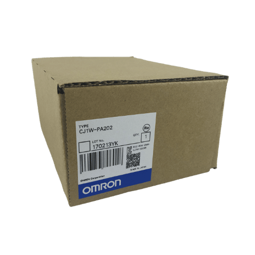
Omron PLC CJ1W-PA202 Supplier in China
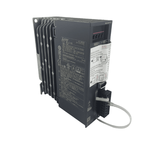
Mitsubishi MR-JE Series 400w Servo Drive MR-JE-40A
Need a Fast Match?
Share your model or spec and our team will help you find the right fit-fast.
- Expert support
- Quick response
- Competitive price
- +86-755-81481609
- [email protected]
You May Also Find These Topics Interesting
CJ2M-CPU13 vs CJ2M-CPU32: Which Omron CPU Should You Buy?
If you are trying to choose between the CJ2M-CPU13 and the CJ2M-CPU32, the real difference is not just the model number. In

Why Choose Allen-Bradley PLCs for Your Project?
Why Choose Allen-Bradley PLCs for Your Project? Struggling with selecting the right PLC for your engineering projects? You’re not alone. Many purchasing
Omron NB HMI Communication Error: PLC Cable, Port, and Settings
An Omron NB HMI communication error usually comes down to one of four things: the wrong PLC driver, the wrong COM port,