
Mitsubishi MR-J4 AL.50 and AL.51: Load, Brake or Servo Sizing Problem?
Table of Contents
AL.50 and AL.51 do not identify an undersized motor by themselves. AL.50 indicates that the load has exceeded the amplifier’s overload-protection characteristic. AL.51 concerns maximum output current flowing continuously, as can happen when a mechanism collides or cannot move. Mitsubishi distinguishes them in its MR-J4 Troubleshooting Manual.
The useful question is what the axis was doing when the demand became excessive. A problem at the first movement after brake release needs a different investigation from one that develops after repeated production cycles.
This guide covers conventional rotary-servo applications using MR-J4-A and MR-J4-B amplifiers. Linear, fully closed-loop and multi-axis configurations have additional model-specific checks.
Read the Detail Number Alongside the Machine Cycle
The detailed code helps establish whether the overload occurred during operation or while stopped.
| Alarm details | Classification in the manual |
|---|---|
| AL.50.1, AL.50.2, AL.50.3 | Overload 1 during operation |
| AL.50.4, AL.50.5, AL.50.6 | Overload 1 during a stop |
| AL.51.1 | Overload 2 during operation |
| AL.51.2 | Overload 2 during a stop |
These entries cover the AL.50 and AL.51 groups, rather than the complete MR-J4 alarm list.
Save the full code, alarm history and operating conditions before resetting. Include the product being handled, cycle time and any recent mechanical or program changes. Where available, preserve a trace of command speed, actual speed and torque/current, together with the effective and peak load readings.
A single peak value without its place in the cycle is difficult to interpret. The same reading could occur during acceleration, against an obstruction or while the servo struggles to hold position.
- Related Product
Need a Replacement Altivar Drive?
Browse new original Altivar drives for maintenance, troubleshooting, and replacement projects.
- New original parts
- Fast response
- Global shipping
When the Mechanism Is Asking for More Torque
Start with what changed.
A new payload, shorter move time or heavier fixture gives a plausible reason for higher demand. If the operating recipe is unchanged, investigate deterioration or an installation problem before reopening the original sizing calculation.
Useful observations include:
- Resistance or abnormal noise appearing at one location in the travel.
- A fault that began after belt tensioning, coupling work or guide replacement.
- Higher demand in one direction than the other.
- Product contact occurring earlier than intended.
- A load that remains high after the acceleration segment has finished.
These observations help choose the next inspection; none proves a cause on its own. For example, a repeatable rise in torque at the same carriage position suggests a local mechanical issue worth examining. It does not establish whether the source is a guide, screw, cable carrier or external contact.
Mechanical inspection must follow the machine’s isolation procedure. Secure gravity-loaded axes and stored energy before releasing a brake or disturbing a coupling. Do not use powered motion to push through a suspected obstruction.
Electrical faults also belong in the investigation. Mitsubishi’s overload remedies include motor-power wiring and feedback connections, as well as load-related causes. That is particularly relevant when the first overload follows motor or cable replacement.
A Brake Command Is Not Proof of Brake Release
On a motor fitted with an electromagnetic brake, the release sequence deserves attention when the axis struggles at startup.
Mitsubishi specifies that the brake has a release delay and that sufficient time must pass before motor operation begins. The timing must be verified on the actual machine. The brake is intended for holding, not routine deceleration. These requirements are explained in the HG-series Servo Motor Instruction Manual, section 1.3.
A PLC output turning on establishes only that the command was issued. It does not establish that the supply reached the brake correctly or that mechanical release finished before the move began.
A qualified technician should compare the intended sequence with the installed circuit and actual timing. Relevant evidence includes the brake command, supply condition and start of motion. Use the specifications for the exact motor; a timing value copied from another axis may not apply.
On a vertical axis, brake testing also changes how the load is supported. The machine’s approved restraint and test procedure must be in place before release. Never bypass the brake to see whether the overload disappears.
- PLC Solutions
Find the Right PLC for Your System
Explore new original PLC CPUs, I/O modules, power supplies, and communication units for maintenance and automation projects.
- New original parts
- Fast response
- Global shipping
Separate the Acceleration Peak From the Whole-Cycle Demand
A servo can face a demanding acceleration segment while carrying a modest load during the rest of the cycle. Another axis may have no dramatic peak but work hard almost continuously. Those conditions require different changes.
Mitsubishi directs AL.50 diagnosis toward effective load ratio and AL.51 diagnosis toward peak load ratio and torque saturation. It also identifies instability or resonance among the AL.50 checks.
Interpret the readings against the motion pattern:
| Observed pattern | Investigation it supports |
|---|---|
| Demand rises sharply during acceleration | Payload, reflected inertia and acceleration requirements |
| Demand remains elevated through the move | Process force, friction or a continuing mechanical load |
| Repeated cycles gradually lead to a trip | Whole-cycle loading, dwell time and operating duty |
| Torque fluctuates while the axis should be settled | Mechanical looseness, vibration or control instability |
| Demand rises but little movement occurs | Obstruction, brake release, wiring or feedback problems |
This is a diagnostic framework, not a substitute for the applicable protection curves.
As an illustrative example, shortening a transfer move while keeping the same travel and payload increases the acceleration demand. A sizing review should use the revised profile. Conversely, if the profile has not changed but the torque trace has, investigate why the physical system now needs more effort.
Any trial change to acceleration or cycle timing should be approved for the machine and documented. An alarm-free slower cycle is useful evidence, but it does not automatically prove that the mechanism is healthy.
What Would Justify a Larger Servo?
A larger motor becomes a credible option when a correctly functioning mechanism still requires more torque or duty capability than the installed system can provide.
That conclusion needs a calculation using the real application. Mitsubishi’s Motorizer sizing software evaluates the mechanism and operating pattern, with results that include effective and peak torque, speed, inertia and regenerative demand.
Prepare the inputs that explain the load:
- Moving mass or rotational inertia, including tooling and product.
- Transmission ratio, screw lead or other mechanism geometry.
- Process forces and gravity loading.
- Acceleration, constant-speed, deceleration and dwell periods.
- Required cycle rate and actual supply conditions.
Then compare the proposed motor–amplifier combination against the complete duty. Nameplate power alone does not describe the torque required at each speed or how frequently it must be delivered.
If the analysis leads to replacement, contact Kwoco with the selected combination and the existing equipment references. Include brake and interface requirements so the inquiry covers more than capacity.
Frequently Asked Questions
Yes. Both groups include stop-related detailed codes. A stationary axis may still be producing torque to hold a load or oppose a command. The manual’s stop-related checks include collision and, for AL.50, hunting during servo-lock. Read the detailed code before assuming the fault belongs to the preceding move.
No. Touch temperature cannot establish brake release. Mitsubishi notes that a motor with its brake released may become hot even without driving. Diagnosis needs the actual release sequence and electrical checks, performed safely against the motor documentation.
Do not assume that a larger amplifier makes the existing motor capable of more continuous work. The proposed combination must be approved, and the motor’s torque-speed capability still matters. Mitsubishi’s sizing process considers both motor and drive selection. Review the complete combination rather than ordering by amplifier capacity alone.
The slow test may reduce acceleration demand, cycle frequency or both. Compare the actual profiles, not just their top speeds. A longer dwell can also change whole-cycle loading. Use the production pattern in the sizing analysis, while investigating any abnormal mechanical resistance separately.
It should not be used for ordinary deceleration. Mitsubishi identifies it as a holding brake and requires attention to its engagement and release timing. Repeatedly applying it as a service brake can create a maintenance problem rather than solve an overload issue. Follow the machine’s designed stopping sequence and the motor brake instructions.
Power your projects with brand-new, original Omron, Mitsubishi, Schneider Servo – in stock, ready now!
Reset Only After the Cause Has Been Addressed
For these overload alarms, Mitsubishi’s reset-table footnote calls for approximately 30 minutes of cooling after resolving the cause. Follow the applicable reset method with the run command disabled and the machine safe to restart.
Cooling is not evidence that the fault has been repaired.
The return-to-service test should cover the condition that caused the trip: the relevant payload, movement and production duty. Compare the new load trace with the earlier one where possible. A single unloaded move cannot establish that a repetitive production cycle is acceptable.
For other codes, see the broader Mitsubishi MR-J4 Servo Alarm Codes guide.
Contact Us
Just fill out your name, email address, and a brief description of your inquiry in this form. We will contact you within 24 hours.
Product Category
Hot Sale Products
Omron CPU Unit CJ2M-CPU32
Omron PLC CJ1W-PA202 Supplier in China
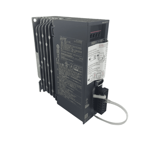
Mitsubishi MR-JE Series 400w Servo Drive MR-JE-40A
Need a Fast Match?
Share your model or spec and our team will help you find the right fit-fast.
- Expert support
- Quick response
- Competitive price
- +86-755-81481609
- [email protected]
You May Also Find These Topics Interesting
RTD and Thermocouples: Vital Sensors for Industrial Automation
In the realm of industrial automation, accurate temperature measurement is crucial for maintaining optimal operations and ensuring product quality. This article delves
Understanding Photoelectric Sensors and Their Applications
Photoelectric sensors are ubiquitous in modern industrial automation, acting as the “eyes” of many systems. They provide crucial non-contact detection of objects,
Which PLC is Mostly Used in Industry? Top PLCs Explained
In the ever-evolving automation industry, one question frequently arises: Which Programmable Logic Controller (PLC) is mostly used in industrial applications? Understanding the landscape of PLC manufacturers and