
Pro-face HMI Communication Error with PLC: Step-by-Step Checks
Table of Contents
The code displayed on the HMI is the best starting point. RHAA065, for example, points toward an Ethernet TCP connection problem. RHAA067 through RHAA070 usually direct the investigation toward serial communication, device settings, wiring, or a disconnected target. Codes RHAA036 through RHAA039 identify address-range or read/write-access problems rather than a broken network.
This guide applies mainly to Pro-face HMIs configured with GP-Pro EX, including commonly installed GP3000, GP4000, GP6000, SP5000, ST6000, STM6000, STC6000, and ET6000 families. Interface availability varies by model. Older panels programmed with GP-PRO/PBIII or other software require their own manuals and error tables.
How to Read a Pro-face Communication Error
Pro-face communication messages contain a prefix, a node or driver name, a three-digit error group, and sometimes an address, IP address, or PLC-returned error code.
For example:
RHAA065 (PLC1): TCP connection open error
The leading letters can vary with the configured Device/PLC driver and connection slot. Pro-face documentation gives RJEA068 as an example of a code that should be interpreted using the same common error definition as RHAA068. Record the complete message, but use the numeric error group to select the first diagnostic path.
Do not clear or power-cycle the HMI before recording:
- Full error code and message
- Node or PLC name
- IP address or device address shown
- HMI model
- PLC model and communication module
- GP-Pro EX project and software version
- Screen and machine state when the error appeared
That information can separate a physical communication loss from one invalid request in minutes.
Quick Reference: Common Pro-face PLC Communication Errors
This is a focused troubleshooting table, not a complete GP-Pro EX error list. Driver-specific errors must be checked in the Device/PLC Connection Manual for the selected PLC.
| Error code | What it usually means | First checks |
|---|---|---|
| RHAA006 | Received data has a parity error | Parity, data length, noise, connector |
| RHAA007 | Received data has a framing error | Baud/data format, wiring, noise |
| RHAA008 | Ethernet driver selected for a display model without Ethernet support | HMI model and GP-Pro EX Display Type |
| RHAA009 | COM port cannot be used or is assigned incorrectly | Duplicate port use, flow control, interface |
| RHAA010 | TCP port overlap or previous connection did not close | Local port allocation, PLC reset, HMI restart after correction |
| RHAA011 | Ethernet connection was closed | Network path, switch, cable, PLC service |
| RHAA012 | UDP port number overlaps | Ethernet and communication port allocation |
| RHAA033-035 | PLC returned an error to initial, read, or write command | PLC error code, protocol settings, requested address |
| RHAA036-037 | Read or write address is outside the PLC range | GP-Pro EX addresses and PLC memory range |
| RHAA038 | HMI tried to read a write-only address | Object or script read target |
| RHAA039 | HMI tried to write a read-only address | Switch, input object, trigger, or script |
| RHAA040-045 | Illegal response or checksum error | PLC settings, data format, cable, noise |
| RHAA049-054 | Indirect, block, or read/write address is invalid | Indirect addressing and full object data length |
| RHAA065 | TCP connection open error | PLC IP, protocol port, power, cable, service |
| RHAA066 | UDP target not found | Target IP, UDP port, network route |
| RHAA067 | No response to initial communication command | Driver, settings, station, cable, PLC state |
| RHAA068 | No response to device read command | Read address, timing, wiring, PLC response |
| RHAA069 | No response to device write command | Write address, permissions, PLC response |
| RHAA070 | Cable disconnected or target powered off | Power, physical link, cable, selected Display Type |
| RHAA072-073 | Read or write requested while the device is off-scan | Communication scan control and background requests |
Safety Before Opening the Cabinet
Many communication faults can be diagnosed from GP-Pro EX, the HMI offline menu, switch indicators, and PLC software without touching live wiring.
Before inspecting serial terminals, adapters, power wiring, or connectors inside a control panel:
- Stop the machine in a controlled state.
- Follow the site’s lockout and electrical-safety procedure.
- Isolate relevant power sources.
- Confirm that hazardous voltage is absent before working near exposed conductors.
- Protect PLC and HMI project backups before changing settings.
Do not reconnect serial wiring or move interface adapters in an energized cabinet unless the equipment documentation and site procedure explicitly permit it.
- Related Product
Need a Replacement Altivar Drive?
Browse new original Altivar drives for maintenance, troubleshooting, and replacement projects.
- New original parts
- Fast response
- Global shipping
Step 1: Decide Whether the Failure Affects All Screens
This is the most useful first split.
Communication fails on every screen
If all PLC values stop updating, investigate the common path:
- PLC power and CPU state
- HMI Device/PLC driver
- HMI COM or Ethernet interface
- Serial or Ethernet communication settings
- Station number or target IP
- Cable, connector, hub, and PLC communication module
The physical link or shared configuration is more likely than an individual screen object.
Communication fails only on one screen
If the error appears only when a particular screen opens, the link may be healthy. A part or script on that screen may be using an unsupported address.
Check:
- Data Displays
- Switches and input objects
- Lamps
- D-Scripts
- Indirect addresses
- Text or array objects spanning multiple words
- Window-specific triggers
Use GP-Pro EX Cross Reference to locate every use of the address shown in the error.
The error appears on all screens, but most PLC data still works
A global function may be polling the bad address in the background. Pro-face specifically identifies these common sources:
- System Data Area
- Alarms
- Sampling and historical trends
- Global D-Script
- Global Window
- Logic programs
Open the GP-Pro EX System Settings and use Peripheral List to review Device/PLC management addresses. Also run Project > Utility > Cross Reference, select All, and inspect addresses associated with the error code.
Step 2: Check the PLC and Network Hardware
Confirm the PLC is powered, in its expected operating mode, and not reporting a CPU, communication-module, or configuration fault.
Then inspect the shared hardware:
- HMI and PLC power supplies
- Ethernet link indicators
- Serial and Ethernet connectors
- Network switch or hub power
- Communication-module seating
- Cable damage near door hinges and machine movement
- Recent maintenance or PLC replacement
If the error began after a PLC download, confirm that the PLC communication configuration was included and activated. If it began after an HMI replacement, confirm that the correct GP-Pro EX project and Display Type were transferred.
Step 3: Verify the Device/PLC Driver in GP-Pro EX
In GP-Pro EX, open:
System Settings > Device/PLC
Check:
- PLC manufacturer
- Driver name
- Series or CPU type
- Connection method
- COM or Ethernet port
- Node or station configuration
- Driver-specific options
Choosing the correct manufacturer is not enough. Mitsubishi serial, Mitsubishi Ethernet, Siemens S7, Omron Host Link, Omron FINS, Modbus SIO, and Modbus TCP drivers use different settings and requests.
The Pro-face Device/PLC Connection Manual is organized by manufacturer and driver. For each driver, check:
- Supported PLC or controller models
- System configuration
- HMI communication settings
- PLC-side settings
- Cable diagrams and adapter part numbers
- Supported device address ranges
- Driver-specific restrictions and error codes
If GP-Pro EX is set for the wrong Display Type, the project can also assign an unavailable interface. RHAA008 indicates that an Ethernet driver was transferred to a model that cannot use Ethernet. RHAA009 can occur when multiple drivers are assigned to the same COM port or when port flow control is unsuitable.
Step 4: Compare GP-Pro EX Settings with the Actual HMI
Do not assume the settings in the project are the settings currently running in the panel.
Enter the HMI offline menu and open:
Peripheral Settings > Device/PLC Settings
Compare the actual HMI settings with the GP-Pro EX project and PLC configuration.
For Ethernet, also check:
Main Unit Settings > Ethernet Local Settings
Project transfer normally applies the GP-Pro EX communication settings to the HMI. A technician may temporarily change settings in offline mode, only to have them replaced by the next project download. Keep the master settings correct in GP-Pro EX.
- PLC Solutions
Find the Right PLC for Your System
Explore new original PLC CPUs, I/O modules, power supplies, and communication units for maintenance and automation projects.
- New original parts
- Fast response
- Global shipping
Step 5: Troubleshoot Serial Communication
Errors RHAA067 through RHAA070 are commonly associated with RS-232C, RS-422, or RS-485 communication.
Confirm the serial interface
Verify that the selected HMI port supports the configured SIO type:
- RS-232C
- RS-422
- RS-485 2-wire
- RS-485 4-wire
Port capabilities differ between Pro-face models. A connector’s shape does not define its electrical interface. Some models support only one communication type on a particular COM port.
Pro-face warns that operation is not guaranteed if the project specifies a communication type unsupported by the display’s serial interface.
Match all communication parameters
Compare the HMI and PLC:
- Baud rate
- Data length
- Parity
- Stop bits
- Flow control
- Station, unit, or node number
RHAA006 and RHAA007 point toward parity or framing problems. Mismatched data format is one cause, but electrical noise and loose connectors can produce the same symptom.
If the PLC has DIP switches or rotary switches for serial settings, read their actual position. Do not rely only on an old electrical drawing.
Use the exact cable diagram
Serial pinouts are driver- and model-specific. Check the Device/PLC Connection Manual for the exact combination of:
- Pro-face HMI model and COM port
- PLC CPU or communication module
- RS-232C, RS-422, or RS-485 interface
- Required Pro-face conversion adapter
- Cable wiring and maximum length
Inspect TX/RX crossing for RS-232C, differential pairs for RS-422/485, signal ground, shield, termination, and any control signals required by the driver.
Do not match A to A or B to B without checking the functional polarity. Equipment manufacturers do not always use A/B labels consistently.
Check station addressing
On a multi-drop serial network, every PLC or controller must have a unique station number. The station selected by the HMI object or driver must exist.
If initial communication times out but wiring and data format look correct, verify:
- PLC station number
- HMI target station
- Gateway or link-unit station
- Multi-link settings
- Duplicate stations
Look for noise and topology problems
If communication fails when a contactor, inverter, servo, or solenoid operates, inspect EMC conditions:
- Separate communication cables from motor and power wiring.
- Check shield termination against the hardware manuals.
- Verify cabinet bonding and protective earth.
- Inspect cable damage at moving door or drag-chain points.
- Confirm the specified RS-485 termination and topology.
Do not add termination or earth connections by guesswork. Follow the Pro-face and PLC wiring diagrams.
Step 6: Troubleshoot Ethernet Communication
Errors RHAA065 and RHAA066 are the main Ethernet connection indicators in this context.
Check all IP addresses
Verify:
- The HMI’s actual IP address and subnet mask
- The PLC or communication module’s actual IP address
- The PLC target IP stored in GP-Pro EX
Also check:
- Duplicate IP addresses
- Incorrect gateway
- Wrong network interface
- DHCP assigning an unexpected address
- PLC replacement with a default IP
- A project copied from another machine
From a PC on the same network, ping both the HMI and PLC. Pro-face recommends this as part of the RHAA065/066 diagnosis.
A successful ping proves IP reachability, not PLC protocol operation. The port, PLC communication service, connection resources, and access settings still need verification.
Verify the protocol port
The HMI destination port must match the PLC driver and PLC-side service. Do not assume that every Ethernet PLC uses the same port.
Review:
- GP-Pro EX Device/PLC port setting
- PLC or Ethernet-module open-connection setting
- TCP versus UDP
- PLC server or protocol enable setting
- Available connection resources
- Firewall or managed-switch rules
The Pro-face connection manual notes that the HMI system initially uses local ports 8000 through 8019. Avoid assigning those as HMI-side communication ports unless the current system configuration has been deliberately changed and verified.
RHAA010 and RHAA012 indicate port overlap conditions. RHAA011 means an established connection was closed, often after a PLC reset or network interruption.
Simplify the network
If settings appear correct:
- Save the original network configuration.
- Put a service PC, HMI, and PLC on a controlled test network.
- Use known-good Ethernet cables.
- Remove unnecessary routers, wireless bridges, and switches from the test path.
- Ping both devices.
- Test the PLC protocol.
Pro-face specifically recommends trying another hub and cable. If direct communication works, restore network components one at a time and check VLANs, switch errors, IP conflicts, routing, and port security.
Step 7: Resolve PLC-Returned and Address Errors
Codes RHAA033 through RHAA035 mean the PLC returned an error to an initial, read, or write request. The decimal and hexadecimal detail is produced by the connected device. Decode it with the PLC manual and the Pro-face driver manual.
Do not replace the HMI because a PLC rejected an unsupported request.
Out-of-range addresses
RHAA036 and RHAA037 mean a requested read or write address is outside the valid range.
Check:
- PLC CPU memory range
- Driver-supported address range
- File, bank, or block number
- Array and string length
- Recipe or data-transfer span
- Indirect address calculation
- Addresses copied from another PLC model
An object can start at a valid address and still cross beyond the valid range because its data length is too large.
Read-only and write-only addresses
RHAA038 means the HMI tried to read a write-only address. RHAA039 means it tried to write to a read-only address.
Review Data Displays, switches, input-enabled objects, triggers, and D-Scripts. An HMI object may perform both a read and a write even if its intended use appears one-directional.
Indirect and block addressing
Codes RHAA049 through RHAA054 identify unknown indirect devices, block ranges that exceed the supported area, or read/write access violations detected by the protocol driver.
Check the calculated device code, base address, offset, and complete data length at runtime. A correct design value can become invalid if the PLC writes an unexpected index.
Step 8: Use Cross Reference and Peripheral List
GP-Pro EX includes two tools that save a great deal of searching.
Cross Reference
Open:
Project > Utility > Cross Reference
Select All as the target. Search the device address shown in the error and review every part, script, alarm, sample, and trigger that uses it.
For RHAA036/037, look for addresses outside the supported range.
For RHAA038, look for a read operation on a write-only address.
For RHAA039, look for a write operation on a read-only address.
Peripheral List
Open the GP-Pro EX System Settings and select Peripheral List. Review the list of Device/PLC management addresses used by functions that communicate across all screens.
This is particularly useful when the same error follows the operator from screen to screen even though normal values continue to update.
- HMI Replacement
Upgrade or Replace Your HMI
Find compatible HMI panels for discontinued models, machine upgrades, and operator interface replacement.
- New original parts
- Fast response
- Global shipping
Step 9: Run the Pro-face COM and LAN Hardware Check
If settings and wiring match the manuals but communication still fails, test the HMI interface itself.
In the HMI offline mode, open:
Maintenance Menu > Check COM1/COM2/LAN
Pro-face provides model-specific loopback patterns for COM-port tests. Use the loopback cable specified for the exact display family. The test reports OK or NG.
Important limits apply:
- The current manual states that this COM/LAN check is unavailable on GPH6000, GP6000, IPC, and SP5000 Open Box models.
- The COM-port check is also unavailable on the AST-3211A MPI port and GP-4107.
- The loopback wiring differs by display family and interface.
- MPI ports are not included in the test.
- A correct LAN check does not verify the PLC application protocol.
An NG result with the correct model-specific loopback setup makes HMI interface damage more likely. Confirm the procedure before arranging repair or replacement.
Step 10: Prove the Repair with a Minimal Test
When a large project contains hundreds of objects, make a test copy of the project.
- Keep the correct Display Type and one Device/PLC driver.
- Enter the verified serial or Ethernet settings.
- Add one read-only object using a known valid PLC address.
- Transfer the test project or use supported simulation.
- Confirm stable communication.
- Add object groups until the error returns.
If the minimal project fails, focus on the common driver, PLC service, interface, and cable.
If it works, the original project contains an invalid address, script, global function, or excessive request condition.
Clearing the Error After Communication Recovers
Fix the cause before restarting equipment.
Depending on the GP-Pro EX error-display settings, online errors can be configured to clear at recovery or on a screen change. Pro-face notes that some read or write communication messages may remain visible even after communication recovers. In that case, change the screen or touch the close control after confirming that live data is updating correctly.
A message that remains displayed is not, by itself, proof that the present communication is still down.
After changing PLC communication parameters, a controlled PLC and HMI restart may be required by the selected driver or hardware. Follow the equipment manuals and machine restart procedure.
Frequently Asked Questions
RHAA065 means the HMI could not open the configured TCP connection to the PLC or device. Check the PLC IP address, protocol port, PLC and hub power, Ethernet cable, GP-Pro EX driver, and whether the PLC communication service is enabled.
A part or script on that screen is probably requesting an invalid, unsupported, or inaccessible PLC address. Use GP-Pro EX Cross Reference to inspect the screen’s Data Displays, switches, lamps, scripts, indirect addresses, and block lengths.
Yes. Ping confirms the IP path, but not the PLC protocol. The GP-Pro EX driver, TCP/UDP port, PLC service, access permission, connection resources, and requested device addresses can still be wrong.
Use the HMI offline-mode Check COM1/COM2/LAN function with the model-specific loopback cable or test procedure. An NG result after following the correct hardware manual points toward an interface fault, while an OK result sends the investigation back to settings, wiring, and protocol.
These codes identify a specific invalid request rather than a total link failure. RHAA036/037 indicate an out-of-range read or write, while RHAA038/039 indicate incorrect access to write-only or read-only devices. Check global functions as well as the current screen.
Power your projects with brand-new, original Omron, Mitsubishi, Schneider HMI – in stock, ready now!
When Replacement Is the Right Decision
Do not replace the HMI until the PLC settings, GP-Pro EX driver, address requests, cable, adapter, network hardware, and interface test have been checked.
Replacement becomes reasonable when:
- The model-specific COM or LAN self-test reports NG.
- The interface has visible physical or surge damage.
- Multiple known-good cables and devices fail on one HMI port.
- The panel repeatedly corrupts or loses its communication configuration.
- An obsolete panel can no longer be repaired economically.
Before sourcing a replacement, collect:
- Complete Pro-face model number, usually beginning with PFX
- Hardware revision and serial information
- GP-Pro EX project backup
- Display Type and screen resolution
- PLC model and communication module
- Driver name and version
- COM interface or Ethernet settings
- Cable and adapter part numbers
- Panel cutout and power requirements
Kwoco can help check a Pro-face HMI, communication cable, or compatible replacement against these details. Sending nameplate photos, rear-port photos, the exact communication error, and the GP-Pro EX project version is more reliable than selecting a panel by screen size alone.
Official Proface References
Contact Us
Just fill out your name, email address, and a brief description of your inquiry in this form. We will contact you within 24 hours.
Product Category
Hot Sale Products
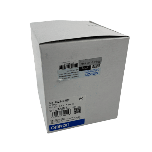
Omron CPU Unit CJ2M-CPU32
Omron PLC CJ1W-PA202 Supplier in China
Mitsubishi MR-JE Series 400w Servo Drive MR-JE-40A
Need a Fast Match?
Share your model or spec and our team will help you find the right fit-fast.
- Expert support
- Quick response
- Competitive price
- +86-755-81481609
- [email protected]
You May Also Find These Topics Interesting
Variable Frequency Drives (VFD): Complete Guide to Motor Control
A comprehensive guide to variable frequency drives (VFDs) – the technology that’s revolutionizing motor control in industrial applications. Whether you’re an engineer,

Understanding Mitsubishi PLC Programming: Languages and Tools
In the fast-evolving world of industrial automation, selecting the right PLC programming language is crucial. Many engineers and technicians grapple with understanding

Top 6 Omron PLC Suppliers in Germany
You need a part. It should be easy to buy. But it isn’t always easy. I talk to buyers from Germany all