
Omron CJ2M PLC Error Codes and Network Troubleshooting
Table of Contents
The CPU section uses the RUN and ERR/ALM indicators, Auxiliary Area flags, the current error code in A400, and the error log. A CJ2M-CPU3[] also has a built-in EtherNet/IP section with MS, NS, COMM, link-speed indicators, and a two-character seven-segment display.
That distinction matters. A solid red ERR/ALM means the CPU has stopped on a fatal error. A flashing red NS indicator, by contrast, can mean that the PLC program is still running while one or more network connections are down.
This guide explains how to separate those conditions, interpret the most useful CJ2M error codes, and troubleshoot FINS and EtherNet/IP communications without changing settings at random.
Scope: CJ2M-CPU1[] and CJ2M-CPU3[] Are Not the Same
First, read the complete CPU model from the front label.
- CJ2M-CPU11/12/13/14/15: No built-in EtherNet/IP port. Ethernet communications require a separate Unit, such as a CJ1W-EIP21 EtherNet/IP Unit or CJ1W-ETN21 Ethernet Unit.
- CJ2M-CPU31/32/33/34/35: Includes a built-in EtherNet/IP port and the network indicators and seven-segment display discussed in this article.
Do not treat CJ1W-EIP21 and CJ1W-ETN21 as interchangeable names.
The CJ1W-EIP21 supports EtherNet/IP tag data links, CIP messages, and FINS communications and is covered by Omron manual W465. The CJ1W-ETN21 is an Ethernet Unit used for functions such as FINS, sockets, FTP, and related Ethernet services; its main network manuals are W420 and W421.
The CPU error information below applies to both CJ2M families. The built-in network display codes apply specifically to CJ2M-CPU3[]. An external communication Unit has its own indicators, settings, and allocated CIO status words.
- Related Product
Need a Replacement Altivar Drive?
Browse new original Altivar drives for maintenance, troubleshooting, and replacement projects.
- New original parts
- Fast response
- Global shipping
Safety and Data Protection Before Troubleshooting
Only qualified personnel should work inside the control cabinet.
Before touching terminals, backplane connectors, Unit switches, or network wiring, stop the machine safely, isolate the required power sources, follow the site’s lockout procedure, and verify the de-energized condition. Do not insert or remove CJ-series Units while power is supplied.
Back up the user program, PLC Setup, I/O table, routing tables, network configuration, symbols, and parameter files before replacing a CPU or communication Unit. An uploaded ladder program alone may not contain everything required to return the machine to service.
Also record the evidence before clearing it:
- Full CPU and communication Unit model numbers
- CPU Unit version and built-in EtherNet/IP section version
- State of every indicator
- Seven-segment code, if present
- A400 value and the full error log
- Machine operating stage when the error occurred
- Recent program, I/O, switch, network, or equipment changes
Start with the Indicators
CPU Indicators
| Indicator state | Meaning | What to do first |
|---|---|---|
| RUN green ON | CPU is in RUN or MONITOR mode and executing the program | Check whether the problem is network-, I/O-, or process-related |
| RUN OFF, ERR/ALM OFF | CPU may be in PROGRAM mode or downloading | Check operating mode in CX-Programmer |
| ERR/ALM red flashing | A non-fatal error is active; CPU operation normally continues | Read A400, Auxiliary flags, and the error log |
| ERR/ALM red solid | A fatal CPU error or watchdog condition has occurred; CPU operation stops | Record the evidence and identify the fatal error before restarting |
When a fatal CPU error occurs, outputs on Basic I/O Units are turned OFF. The IOM Hold setting does not keep physical outputs ON through a fatal CPU stop.
Built-in EtherNet/IP Indicators on CJ2M-CPU3[]
| Indicator | Normal or diagnostic meaning |
|---|---|
| MS green ON | Built-in EtherNet/IP section is operating normally |
| MS red flashing | A recoverable module-side error or setting error exists |
| MS red ON | A fatal error exists in the built-in network section |
| NS green ON | Required tag data links or message connections are established |
| NS green flashing | The port is online, but the expected connections are not all established |
| NS red flashing | A recoverable network error exists, commonly a connection timeout |
| NS red ON | A fatal network error exists, such as duplicate IP detection |
| COMM yellow flashing or ON | Ethernet frames are being transferred |
| 100M or 10M ON | Physical link is established at the indicated speed |
The seven-segment display normally shows the rightmost byte of the local IP address in hexadecimal. During a network error, it can alternate an error code with the rightmost byte of the affected target IP address. Photograph the full sequence, not just one frame.
How CJ2M Error Codes Are Stored
The most serious current CPU error code is stored in A400. That word is useful, but it is not the whole diagnosis.
The CJ2 CPU keeps up to 20 error records in A100 through A199. Each record uses five words for the error code, error information, and time of occurrence. A300 is the error-log pointer.
In CX-Programmer, connect to the PLC and open the PLC Errors window, then select the Error Log tab. Read all entries before clearing them. If several errors occurred together, A400 reports the highest-severity active error, which may be the consequence rather than the first event.
For an intermittent machine, the sequence often tells the story. A Basic I/O error followed by a fatal I/O bus error points in a different direction from a memory error followed by a watchdog stop.
- PLC Solutions
Find the Right PLC for Your System
Explore new original PLC CPUs, I/O modules, power supplies, and communication units for maintenance and automation projects.
- New original parts
- Fast response
- Global shipping
Omron CJ2M Fatal Error Code Quick Reference
The following table covers the fatal errors that are most useful in field troubleshooting. It is not a substitute for the complete W472 error tables.
| A400 code | Official error category | Typical cause | First corrective action |
|---|---|---|---|
| 809F | Cycle Time Exceeded | PLC cycle exceeded the maximum watch cycle time in PLC Setup | Check recent logic changes, loops, interrupt loading, and actual maximum cycle time before changing the limit |
| 80C0 to 80C7, 80CE, 80CF | I/O Bus Error | Loose or damaged connecting cable, missing End Cover, rack transfer failure, or faulty Unit/backplane connection | Inspect the rack, End Cover, I/O connecting cables, and the location recorded in A404 |
| 80E0 | I/O Setting Error | Actual Units do not match the registered I/O table | Compare the physical rack with the I/O table and create or transfer the correct table |
| 80E1 | Too Many I/O Points | I/O capacity, rack, interrupt-input, or pulse-I/O configuration limit exceeded | Correct the hardware configuration and power-cycle after verification |
| 80E9 | Unit Number Duplication | Two Special I/O or CPU Bus Units use the same Unit number | Set unique Unit numbers with power OFF, then create/verify the I/O table |
| 80EA | Rack Number Duplication | Duplicate rack/allocation setting | Correct the rack or allocation settings and restart |
| 80F0 | Program Error | No END, invalid instruction, illegal memory access, task error, or user program overflow | Use the error information and stop address in A294 to A299 to locate the program fault |
| 80F1 | Memory Error | Checksum or access error in user program, PLC Setup, I/O table, routing table, or CPU Bus Unit setup | Identify the affected memory area from A403, then retransfer or re-create only that data |
| 80F2 | Version Error | Program uses a function unsupported by the installed CPU Unit version | Use a compatible program or an appropriate CPU Unit version |
| 80F4 | Memory Card Transfer Error | Automatic startup transfer failed or required files/card conditions are incorrect | Inspect the Memory Card, transfer files, DIP-switch/startup settings, and file compatibility |
| C101 to C2FF | User-defined fatal error from FALS(007) | Ladder program deliberately generated a fatal error | Identify the FALS number and trace the machine condition that triggered it |
Error 809F: Cycle Time Exceeded
809F means the CPU cycle exceeded the maximum cycle time configured in PLC Setup.
Do not immediately raise the limit. First look for a recent online edit, a loop that no longer exits, excessive table processing, a communications instruction waiting pattern, or an interrupt task that now runs too long. Omron provides maximum interrupt-task processing information in Auxiliary memory, including A440, which can help separate cyclic-program loading from interrupt loading.
If the normal machine cycle has genuinely changed and the measured worst-case time remains acceptable for the process and safety design, the watch cycle setting can be reviewed. It should never be increased merely to hide runaway logic.
Errors 80C0 to 80CF: I/O Bus Error
An I/O bus error means the CPU could not exchange data correctly across the CJ rack system.
Read A404 before disturbing the rack because it identifies the error location. In Omron’s table, information value 0E hexadecimal indicates a missing End Cover, while 0F means the location could not be determined.
With power isolated, check:
- The End Cover is installed at the right end of every rack.
- Each Unit is fully seated and its locking mechanism is engaged.
- CPU Rack and Expansion Rack connecting cables are undamaged and firmly fitted.
- No connector pins are bent, contaminated, or under mechanical strain.
- The Power Supply Unit has adequate capacity and stable input power.
If the same location returns after reseating and cable substitution, test the affected Unit and rack components methodically. Replacing the CPU first is rarely the best first move for a location-specific I/O bus fault.
Error 80E0: I/O Setting Error
80E0 occurs when the connected Units do not agree with the registered I/O table.
This commonly follows a Unit replacement, a rack rearrangement, a downloaded project from another machine, or an I/O table created for a different CJ2M configuration. Compare model numbers, slot positions, Unit numbers, and the actual rack count with the project.
Do not create a new I/O table until you understand why it differs. On a working production machine, blindly accepting the present hardware can hide a wrong or missing Unit. Once the hardware is confirmed correct, create or transfer the matching I/O table and verify it again.
Error 80E9: Unit Number Duplication
CPU Bus Units and Special I/O Units use front-panel Unit number switches for data allocation and status areas. Two Units with the same number can stop startup with 80E9.
Power OFF before changing any switch. Assign a unique number appropriate to the Unit type and project allocation, restore power, and then verify the I/O table and software settings. Auxiliary words A410 through A416 help locate the duplicated Unit numbers.
Error 80F0: Program Error
80F0 is a category, not a single programming mistake. It can include an instruction-processing error, invalid indirect BCD address, illegal memory access, task error, missing END, invalid instruction, or user-memory overflow.
The error information and program stop address in A294 through A299 are more useful than the category code alone. Open the matching program and task in CX-Programmer, inspect the instruction at and immediately before the stop address, and check indirect addresses and index registers using the values present when the error occurred.
After fixing the logic, perform a controlled test. A program error caused by a rare recipe value or array index may not reappear during a simple idle run.
Error 80F1: Memory Error
Use A403 to determine which memory area failed its check:
| A403 bit | Affected area | Appropriate recovery |
|---|---|---|
| A403.00 | User program | Transfer a verified program again |
| A403.04 | PLC Setup | Initialize and re-enter or transfer the verified PLC Setup |
| A403.05 | I/O table | Initialize and create/transfer the correct I/O table |
| A403.07 | Routing table | Initialize and transfer the verified routing table |
| A403.08 | CPU Bus Unit setup | Initialize and transfer the verified Unit setup |
Avoid initializing the entire PLC when only one data area is identified. If the error repeatedly returns after a known-good transfer, with stable power and correct operating conditions, CPU replacement becomes a reasonable possibility.
Common Non-Fatal CJ2M Error Codes
With a non-fatal error, ERR/ALM flashes and the CPU normally continues running. That does not make the condition harmless: an affected I/O Unit, network, battery, or task can still stop part of the machine.
| A400 code | Error category | Practical checks |
|---|---|---|
| 008B | Duplicated Refreshing Error | Look for competing IORF, FIORF, IORD, or IOWR operations between cyclic and interrupt tasks; check A426 |
| 009A | Basic I/O Error | Inspect the indicated Basic I/O Unit, external supply, output fuse, and field wiring; use A408 |
| 009B | PLC Setup Error | Review invalid or unsupported PLC Setup values and recent configuration transfers |
| 00D1 | Option Board Error | Reseat or replace the front Option Board after safe isolation; check A315.13 |
| 00F1 | Backup Memory Error | Built-in flash backup write failed; Omron specifies CPU Unit replacement |
| 00F2 | Tag Memory Error | Retransfer the program and network-symbol/tag information, then verify the project |
| 00F3 | System Work Error | Online-edit work memory problem; transfer the verified program again |
| 00F7 | Battery Error | Backup battery is missing or low while battery-error detection is enabled |
| 0200 to 020F | CPU Bus Unit Error | Use A417 and the code suffix to identify the affected Unit number |
| 0300 to 035F, 03FF | Special I/O Unit Error | Read the Unit’s own status area and manual; the CPU code only identifies the category/Unit |
| 0400 to 040F | CPU Bus Unit Setting Error | Check Unit switches, setup data, I/O table, and network configuration |
| 0500 to 055F | Special I/O Unit Setting Error | Verify Unit parameters and hardware switches against the project |
| 41xx to 42FF | User-defined non-fatal error from FAL(006) | Find the FAL number and trace the programmed alarm condition |
For a Battery Error, back up the PLC before maintenance and use the battery model and replacement procedure specified for the installed CPU. Disabling battery detection is appropriate only when the system was intentionally engineered for battery-free operation and loss of retained data and clock behavior has been considered.
CJ2M-CPU3[] Built-in EtherNet/IP Display Codes
The following codes appear on the built-in port’s seven-segment display. They are not A400 CPU error codes.
| Display | Omron error description | First checks |
|---|---|---|
| H1 | Duplicate Unit Number | Check the built-in port Unit number against all CPU Bus Units |
| H4 | Node Address Setting Error | Set a valid, unique FINS node address from 01 to FE |
| H7 | I/O Table Not Registered | Create or transfer the correct I/O table after confirming hardware |
| H9 | I/O Bus Error | Diagnose the CPU rack and I/O bus; check the CPU error information |
| HA | CPU Memory Error | Read the CPU error log and A403 before retransferring data |
| HC | Routing Table Error | Verify and transfer the correct routing table |
| HH | CPU Fatal Error | Diagnose the solid ERR/ALM condition on the CPU section |
| C6 | Multiple Switches ON | Check front-panel switch conditions and Unit setup |
| C8 | Node Address Setting Changed During Operation | Restore the intended setting and restart after power is safely removed |
| d5 | Verification Error, target nonexistent | Confirm target power, IP address, node identity, and the configured target entry |
| d6 | Connection Failed | Inspect the failed connection in Network Configurator and verify target tags, size, RPI, and resources |
| d9 | Tag Data Link Error | One or more tag links are abnormal; find the affected target and underlying connection status |
| E1 | Ethernet Link Not Detected | Check cable, switch port, connector, and link-speed indicators |
| E3 | Server Connection Error | Identify the configured service/server and verify its address and reachability |
| E8 | Device Parameters Error | Compare downloaded network parameters with the installed hardware and Unit version |
| E9 | Memory Access Error | Record the code and Unit version; retry a verified transfer, then evaluate hardware if it returns |
| EA | IP Advanced Settings Error | Correct invalid advanced IP parameters |
| F0 | IP Address Duplication | Find the device using the same IP, assign unique addresses, then restart the port/PLC as required |
| F2 | Ethernet Basic Settings Error | Correct the basic Ethernet configuration |
| F3 | Address Mismatch | Check the selected FINS/IP conversion method and the relationship between node and host numbers |
| F4 | Communications Controller Error | Record version and conditions; power-cycle only after saving evidence and checking official guidance |
Codes H2, H3, H6, H8, Hb, Hd, HE, and HF identify additional CPU, built-in-port, backup, servicing, refresh, or watchdog conditions. For these codes, use the complete W472 table and the CPU error log rather than inferring a cause from the display alone.
- HMI Replacement
Upgrade or Replace Your HMI
Find compatible HMI panels for discontinued models, machine upgrades, and operator interface replacement.
- New original parts
- Fast response
- Global shipping
Troubleshooting d5, d6, and d9 Tag Data Link Errors
d5: Verification Error
d5 indicates that the configured target could not be verified, including a target that does not exist at the expected address.
Check whether the target is powered and physically linked, then compare the configured IP address and device identity with the actual node. If a device was replaced, confirm that the Network Configurator project still matches its model, revision, assembly/tag definitions, and network address.
The alternating IP-byte display is valuable here. Convert the hexadecimal byte to decimal and compare it with the target list. For example, 64 hexadecimal corresponds to decimal 100.
d6: Connection Failed
d6 means a configured EtherNet/IP connection could not be established.
Open Network Configurator, go online through a known-good path, and inspect the connection status for the affected node. Verify:
- Originator and target IP addresses
- Target tag names or assemblies
- Input and output data sizes
- Requested packet interval
- Multicast/unicast settings where applicable
- Target connection capacity and existing connections
- Whether the target program or configuration changed
Do not simply download an old network file to a replacement device. A different revision or tag structure can require an updated configuration even when the product family is the same.
d9: Tag Data Link Error
d9 is an overall tag-data-link error, not the root cause. One target can be down while other links remain healthy.
Use the NS state, seven-segment target byte, Network Configurator connection monitor, and the built-in port’s allocated status data to identify the failed connection. Then troubleshoot the underlying d5, d6, timeout, target, or configuration condition.
If d9 appears only during machine startup, compare PLC boot time, managed-switch startup, target-device boot time, and when the control logic begins evaluating network status. The connection may recover automatically, but the PLC program should not treat stale or unverified network data as valid process data.
Troubleshooting F0 Duplicate IP Address
When the built-in port detects another device responding for its IP address, it reports F0 and the Ethernet interface stops normal communications. The duplicate-IP status remains until the conflict is corrected and the Unit is restarted as required.
Use this sequence:
- Disconnect the new or recently serviced device most likely to contain the duplicate address.
- From an engineering PC on the same subnet, inspect the ARP table and switch MAC-address table if available.
- Compare the PLC IP with HMI, drive, vision system, replacement PLC, and maintenance-laptop addresses.
- Assign a unique static address according to the site’s network plan.
- Check for a second device that was temporarily powered down; otherwise the conflict may return later.
Pinging the PLC is not enough to prove that the reply came from the PLC. Check the MAC address and indicator state.
FINS Node Address and IP Address Rules
The built-in port has a hexadecimal FINS node-address switch setting from 01 to FE. The node number must be unique on the FINS network. The Unit number must also be unique among CPU Bus Units in the PLC system.
With Omron’s automatic IP-address generation method, the FINS node address must equal the host-number portion of the IP address. At factory defaults, node 01 corresponds to 192.168.250.1.
If the project uses an IP table or combined conversion method, the node and IP host number do not have to match, but the routing and conversion tables must be correct and every IP and FINS node must remain unique.
Default FINS/UDP and FINS/TCP port numbers are 9600. A firewall rule, NAT device, VPN adapter, or second network interface on the engineering PC can block or misroute those packets even when ICMP ping succeeds.
Always power OFF before changing the physical Unit number or node-address switches. A node-address change during operation is reported as C8 and does not become a valid online change merely because the switch moved.
When CX-Programmer Cannot Connect to a CJ2M over Ethernet
Work from the bottom of the network stack upward.
1. Confirm the Exact Connection Path
For a CJ2M-CPU3[], the cable may connect to the built-in EtherNet/IP port. For a CJ2M-CPU1[], identify the external CJ1W-EIP21 or CJ1W-ETN21 and its Unit number. CX-Programmer settings must match the actual interface.
If Ethernet settings are unknown, use the CPU’s USB peripheral port as a local diagnostic path. Connecting by USB lets you inspect the PLC mode, CPU errors, IP settings, I/O table, routing table, and Unit setup without relying on the failed Ethernet route.
2. Check Physical Link
Look for 100M or 10M on the built-in port and a link indication on the Ethernet switch. Use a known-good shielded twisted-pair cable of the appropriate category and a known-good switch port.
No link means subnet masks and FINS nodes are not yet the problem.
3. Check the Engineering PC
Give the PC a compatible, unique IPv4 address and subnet mask. Temporarily identify which adapter CX-Programmer is using, especially when Wi-Fi, VPN, virtual-machine, and USB-Ethernet adapters are active together.
Do not disable security controls permanently. If a firewall test is required, follow the site’s policy and restore the protection immediately after identifying the required application or port rule.
4. Verify PLC IP, FINS Node, and Conversion Method
Read the PLC settings online through USB where possible. Compare the physical node switch, IP address, subnet mask, FINS/IP conversion method, routing table, and CX-Programmer network settings.
If automatic address generation is selected, a mismatch between the FINS node and IP host number can produce F3.
5. Test in Layers
Check link first, then ARP/MAC identity, then ping, then FINS/CIP service. A successful ping proves only basic IP reachability. It does not confirm that FINS routing, TCP/UDP port 9600, EtherNet/IP connections, or CX-Programmer’s selected network path is correct.
External CJ1W-EIP21 and CJ1W-ETN21 Troubleshooting
For an external Unit, start with its Unit number and the allocated CIO status words associated with that number. A CPU Bus Unit Error in the CPU can identify the affected Unit, while the communication Unit’s indicators and status area provide the network detail.
For CJ1W-EIP21, use Omron W465 and Network Configurator. Check MS, NS, link/activity, Unit number, node/IP settings, tag-link connection status, and the Unit’s error log.
For CJ1W-ETN21, use W420 for network construction and W421 for application services. Its FINS, socket, FTP, mail, and clock functions are configured and diagnosed differently from EtherNet/IP tag data links. A CJ1W-ETN21 problem should not be chased with a d9 checklist intended for the CJ2M-CPU3[] built-in EtherNet/IP port.
A Practical CJ2M Troubleshooting Workflow
Step 1: Preserve the Evidence
Photograph the CPU and communication indicators, record the display sequence, and upload the PLC errors and network status before clearing anything.
Step 2: Decide Whether the CPU Has Stopped
If ERR/ALM is solid and RUN is OFF, diagnose the CPU fatal error first. If RUN remains ON and only NS is red or flashing, protect the process from invalid network data while you diagnose the connection.
Step 3: Read the Right Diagnostic Source
- CPU error: A400, A401/A402 flags, error-information words, and error log
- I/O or CPU Bus Unit: CPU code plus the Unit’s allocated status words
- Built-in EtherNet/IP: MS/NS, seven-segment code, target byte, and Network Configurator
- FINS engineering connection: physical link, IP path, node/routing settings, and port access
Step 4: Check What Changed
Recent Unit replacement, I/O-table creation, network download, switch change, IP reassignment, online edit, cabinet work, or upstream power problem often narrows the diagnosis faster than the error description alone.
Step 5: Correct One Cause at a Time
Avoid changing the I/O table, routing table, IP settings, and ladder program in one attempt. Make one verified correction, restart only when the manual requires it, and check whether the same original code returns.
Step 6: Run a Controlled Test
Confirm that the CPU returns to the intended mode, outputs are safe, every required network connection is established, and the machine logic validates communications before using received data.
Frequently Asked Questions
A solid red ERR/ALM indicates a fatal CPU error or watchdog condition. The CPU stops and Basic I/O outputs are turned OFF. A flashing red ERR/ALM indicates a non-fatal error; the CPU normally continues executing, but the affected function still needs diagnosis. Read A400 and the full error log in both cases.
d9 means one or more EtherNet/IP tag data links are abnormal. It is not a reset instruction. Use the alternating target IP byte and Network Configurator connection monitor to find the failed link, correct the target power, address, tag/assembly, data-size, RPI, or resource problem, and then verify that NS returns to green. Do not clear it by repeatedly cycling PLC power.
Ping confirms basic IP reachability only. CX-Programmer can still fail because of the wrong network driver or PC adapter, an incorrect FINS node or routing table, a blocked FINS/TCP or FINS/UDP port, a node/IP conversion mismatch, or a connection aimed at the wrong communication Unit. Connect through USB to inspect the actual PLC and network settings when possible.
Yes, but it does not have a built-in EtherNet/IP port. A compatible external EtherNet/IP Unit such as CJ1W-EIP21 is required. A CJ1W-ETN21 provides Ethernet services but is a different product and does not replace the EtherNet/IP tag-data-link function of CJ1W-EIP21.
Code 00F7 is normally a non-fatal Battery Error, so the CPU can continue running. However, retained data and the clock can be lost after power is removed if the battery is depleted or disconnected. Back up the PLC and replace the specified battery according to the CJ2 hardware manual rather than postponing it until the next shutdown.
Power your projects with brand-new, original Omron, Mitsubishi, Schneider PLC – in stock, ready now!
When Replacement Is Justified
Do not replace a CJ2M because of 80E0, 80E9, d5, d6, d9, E1, F0, or F3 until the related configuration, switches, cabling, target devices, and network addresses have been checked. These codes usually point to a system condition rather than failed CPU electronics.
Replacement becomes more reasonable when a known-good program and configuration have been restored correctly, power and rack conditions are stable, connected hardware has been isolated or tested, and an internal memory, watchdog, communication-controller, or hardware error returns consistently.
Match a replacement by the full model and Unit version. Confirm program capacity, built-in EtherNet/IP requirement, pulse-I/O configuration, Option Board, Memory Card, network setup, and compatibility of the saved project. A CJ2M-CPU15 is not a drop-in substitute for a CJ2M-CPU35 when the machine uses the built-in EtherNet/IP port.
Kwoco can help identify a suitable Omron CJ2M CPU, CJ1W-EIP21, CJ1W-ETN21, I/O Unit, cable, or battery when the original part is difficult to source. Send the full nameplate photos, Unit versions, rack layout, active error codes, and CX-Programmer backup; those details are much more useful than the PLC family name alone.
Official Omron References
Contact Us
Just fill out your name, email address, and a brief description of your inquiry in this form. We will contact you within 24 hours.
Product Category
Hot Sale Products
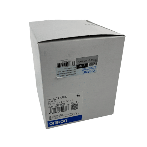
Omron CPU Unit CJ2M-CPU32
Omron PLC CJ1W-PA202 Supplier in China
Mitsubishi MR-JE Series 400w Servo Drive MR-JE-40A
Need a Fast Match?
Share your model or spec and our team will help you find the right fit-fast.
- Expert support
- Quick response
- Competitive price
- +86-755-81481609
- [email protected]
You May Also Find These Topics Interesting
Best Omron PLC Alternatives for Discontinued Models
A discontinued Omron PLC does not always indicate the entire control system should be redesigned quickly. Often the most safe choice is

Transforming the Future of Industrial Automation: Insights for Automation Engineers
Step into a world where machines think and processes are automated. Industrial automation is transforming industries, reshaping how we manufacture, control, and
Troubleshooting Common PLC Failures: A Guide to Programmable Logic Controllers
Programmable Logic Controllers (PLCs) are the backbone of modern automation, orchestrating the seamless operation of machinery and industrial processes. However, like any