
PLC and HMI Communication Checklist: RS-232, RS-485, Ethernet
Table of Contents
The quickest way to solve the problem is to check the connection in layers. Start with power and the physical interface, then move through the cable, communication settings, protocol, station or IP address, and finally the HMI tags.
This checklist applies to many PLC and HMI combinations from Mitsubishi, Omron, Schneider Electric, Weintek, Pro-face, Siemens, and other automation brands. The troubleshooting logic is general, but connector pinouts, driver options, and PLC settings remain model-specific. Keep the manuals for both devices beside you while testing.
The Six Layers of a PLC-HMI Connection
A working communication link needs every layer below to be correct.
| Layer | What to verify | Typical failure symptom |
|---|---|---|
| Device state | Power, RUN status, CPU errors, HMI startup | No connection under any condition |
| Electrical interface | RS-232, RS-422/485, or Ethernet | No response; possible port or adapter mismatch |
| Cable and topology | Pinout, polarity, shield, termination, switch path | No response or intermittent communication |
| Link settings | Baud rate and framing, or IP configuration | Timeout, framing errors, unreachable device |
| Protocol and route | HMI driver, TCP/UDP port, station, network, unit number | Physical link works but PLC still does not respond |
| Application data | Register address, data type, access rights | Some tags fail while communication otherwise works |
Do not jump from a timeout message straight to replacing hardware. A green Ethernet link LED proves that a physical link exists; it does not prove that the HMI is using the right PLC driver. In the same way, correct RS-485 voltage levels do not prove that the baud rate or slave address is correct.
Before You Change Any Settings
Record the current condition first. This is especially important on a machine that was communicating before maintenance.
- Photograph the PLC and HMI nameplates, port labels, cable ends, DIP switches, and termination switches.
- Record the exact HMI error message and any PLC error code.
- Note whether the fault affects every screen, one device, or only certain tags.
- Ask what changed immediately before the problem: HMI download, PLC replacement, cable work, network change, firmware update, or power outage.
- Back up the PLC program, HMI project, communication settings, and recipes when possible.
- Save the original parameter values before editing them.
Power down and isolate equipment before moving serial wires, changing terminal connections, or checking resistance. Confirm that stored energy has discharged according to the equipment manuals. Many PLC and HMI serial ports are not isolated, so live rewiring can damage a port or create a ground fault.
Five-Minute First-Pass Checklist
Run these checks before opening the software.
- Confirm that the PLC is powered and not stopped by a fatal CPU or I/O error.
- Confirm that the HMI has completed startup and loaded the intended project.
- Check the exact port used at both ends. A device may have separate COM1, COM2, Ethernet, USB host, and USB programming ports.
- Identify the electrical interface from the manual, not from the connector shape. A DB9 or RJ45 connector can carry different signals on different products.
- Reseat removable connectors and inspect for loose terminals, bent pins, damaged latches, corrosion, and pulled shield clamps.
- Check Ethernet link/activity indicators or serial transmit/receive indicators, if available.
- Compare the installed cable with the official connection diagram for the exact PLC-HMI pair.
- Restore any connector, terminator, adapter, or switch that was disturbed during recent work.
If the link has never worked, suspect selection, wiring, and configuration. If it worked for months and suddenly stopped, put recent maintenance, connector condition, electrical noise, power quality, and hardware status near the top of the list.
- Related Product
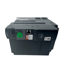
Need a Replacement Altivar Drive?
Browse new original Altivar drives for maintenance, troubleshooting, and replacement projects.
- New original parts
- Fast response
- Global shipping
RS-232 Communication Checklist
RS-232 is intended for short, point-to-point communication. It is still common on compact PLCs, older operator panels, barcode readers, and programming connections.
1. Confirm That Both Ports Are Really RS-232
An RS-232 port cannot be wired directly to an RS-485 port. If one side is RS-232 and the other is RS-422/485, use a suitable industrial converter and confirm whether the system needs two-wire or four-wire operation.
Do not assume that every 9-pin connector is RS-232. Some PLCs use a DB9 connector for RS-422, RS-485, or a manufacturer-specific pin arrangement. Check the port specification and pinout for the exact model and option board.
2. Verify the Cable Pinout
At minimum, an RS-232 data link normally needs transmit data, receive data, and signal common. Transmit at one device must reach receive at the other.
Depending on whether the ports are wired as DTE or DCE, the correct cable may be straight-through or crossed. This is why a standard PC serial cable is not automatically the correct PLC-HMI cable.
Check these points against the official connection drawing:
- TXD at one end goes to the required RXD pin at the other.
- RXD returns to the correct TXD pin.
- Signal ground/common is connected as specified.
- RTS, CTS, DTR, DSR, or other handshake pins are wired or looped only when the devices require them.
- Connector shells and cable shields are terminated according to the manufacturer drawing.
RS-485 termination resistors do not belong on an RS-232 link.
3. Match Every Serial Setting
Both devices must agree on:
- Protocol or communication mode
- Baud rate
- Data length
- Parity
- Stop bits
- Station, unit, or node number when the protocol uses one
- Checksum or frame mode where configurable
One wrong item is enough to stop communication. A common field mistake is matching the baud rate while overlooking parity or data length.
Also confirm that the HMI project is assigned to the physical port where the cable is connected. Configuring COM1 and plugging the cable into COM2 produces a very convincing “hardware fault.”
4. Use a Minimal Point-to-Point Test
Disconnect nonessential adapters and extension leads. Place the HMI and PLC close together and test with one known-good cable built to the official diagram.
If the simplified link works, add the removed components back one at a time. This quickly identifies a bad converter, long extension, connector, or grounding issue.
RS-485 Communication Checklist
RS-485 is used where longer distances, multidrop networks, or better noise immunity are needed. Most PLC-HMI problems on RS-485 come from polarity, topology, station settings, termination, or a missing signal reference.
1. Identify Two-Wire or Four-Wire Operation
Two-wire RS-485 uses one balanced data pair for both transmit and receive. Four-wire communication uses separate transmit and receive pairs. The PLC, HMI driver, converter, and wiring must all be configured for the same method.
For Modbus over two-wire RS-485, the official Modbus guide shows a balanced pair plus a Common conductor. Treating the link as only “two wires” and omitting the reference conductor can make communication unstable, especially when devices have different ground potentials.
2. Verify Polarity by Function, Not by Letter Alone
Manufacturers do not always use A and B labels consistently. One manual may show A/B, another D+/D-, and another SDA/SDB or RDA/RDB.
Follow the pin numbers and signal definitions in both manuals. For Modbus terminology, the current serial line guide associates D1 with B/B’ and D0 with A/A’, but the equipment connection drawing remains the final authority.
If polarity is reversed, the usual symptom is no valid response even though the cable has continuity. Power down before correcting the wiring.
3. Inspect the Bus Topology
Use a trunk or daisy-chain arrangement with short device branches where the product manuals require it. Long star branches create reflections and become increasingly troublesome as cable length and baud rate rise.
Check for:
- A continuous main bus rather than several long star cables
- Short stubs from the trunk to each station
- Shielded twisted-pair cable with the impedance specified for the network
- Data cable routed away from motor leads, contactors, braking resistors, and other high-noise conductors
- Shield bonding and protective grounding that follow the equipment and site EMC instructions
- No accidental connection between the signal pair and protective earth
There is no single universal maximum distance for every RS-485 installation. The usable length depends on baud rate, cable characteristics, topology, number of loads, isolation, and the requirements of the connected products.
4. Check Termination and Biasing
On a passive RS-485 trunk, line termination normally belongs at the two physical ends of the main bus, not at every device. Some PLCs and HMIs include switchable termination internally; others require an external resistor.
Do not add a resistor just because the network is failing. Too many terminators load the driver, while missing end termination can cause reflections. Confirm the resistor value, switch position, and whether termination is already built into each product.
Biasing, also called polarization or failsafe bias, should be applied only as required by the network design. The Modbus serial guide recommends one polarization point for a bus that needs it. Several devices applying strong bias at once can produce another fault instead of fixing the first one.
5. Match Protocol and Station Settings
For Modbus RTU, confirm that every node uses the same serial format and that each server/slave has a unique address. Address 0 is reserved for broadcast in Modbus serial communication, and a broadcast request does not receive a response.
For manufacturer-specific protocols, verify all required values, which may include PLC unit number, network number, node number, CPU type, link mode, or checksum setting.
Also make sure only the intended master/client is controlling the bus. Two masters transmitting without a protocol designed for multi-master operation will cause collisions and irregular timeouts.
6. Isolate the Network One Node at a Time
If a multidrop network is unstable, test the HMI with only the PLC connected. Then reconnect one station and one cable section at a time.
A branch that makes the entire bus fail often points to reversed polarity, a duplicate address, a short circuit, an extra terminator, an incompatible serial setting, or a damaged transceiver on that branch.
- PLC Solutions
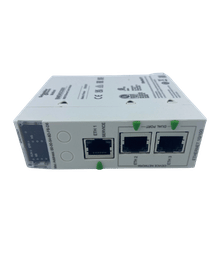
Find the Right PLC for Your System
Explore new original PLC CPUs, I/O modules, power supplies, and communication units for maintenance and automation projects.
- New original parts
- Fast response
- Global shipping
Ethernet Communication Checklist
Ethernet makes physical wiring easier to expand, but it adds several configuration layers. A successful ping is useful; it is not a complete PLC communication test.
1. Confirm the Physical Link
Check the link indicators at the HMI, PLC, and switch. No link LED usually means you should inspect the cable, connector, port, switch power, or interface settings before changing the HMI driver.
Try a known-good patch cable and another switch port. Inspect cabinet RJ45 plugs for broken latches, poorly seated field connectors, shield damage, and contamination.
If communication fails only when a drive, welder, or contactor operates, inspect cable routing, shielding, cabinet bonding, and the switch power supply as well as the network configuration.
2. Verify the Live IP Configuration
Check the values currently active in the devices, not only the values shown in an offline project.
- HMI IP address
- PLC or communication-module IP address
- Subnet mask
- Default gateway when routing is required
- Duplicate IP addresses
- Correct Ethernet interface when a device has more than one
- DHCP versus fixed-address behavior
For a direct test on one subnet, give the engineering PC, HMI, and PLC unique addresses in the same subnet. Disconnect the test cell from the production network first if changing addresses could create a conflict.
3. Use Ping Correctly
Ping confirms that an IP path exists and that the target responds to ICMP. It does not confirm any of the following:
- The HMI is using the correct PLC driver.
- The PLC application service is enabled.
- The correct TCP or UDP port is open.
- The station, rack, slot, network, or unit number is correct.
- The HMI has permission to read or write the requested memory.
If ping fails, stay with the cable, link, address, subnet, route, VLAN, firewall, and duplicate-address checks. If ping succeeds but the HMI still times out, move upward to the protocol and application settings.
4. Check the HMI Driver and PLC Service
Select the driver for the actual PLC family and communication method, not just the manufacturer name. For example, two controllers from the same brand may use different Ethernet protocols or require different HMI drivers.
Compare these settings with the PLC program and hardware configuration:
- Protocol selection
- TCP or UDP transport
- Destination port number
- PLC model or CPU family
- Station, node, network, rack, slot, or unit number
- Local and remote connection parameters
- PLC-side server, open setting, or connection resource
- Read/write access and security settings
A port number should come from the product manual or the PLC configuration. Do not change it at random because an online list calls it a “standard PLC port.”
5. Check the Network Between the Devices
When the HMI and PLC are not directly connected, verify the full path:
- Managed-switch VLAN assignment
- Router and gateway configuration
- Access control lists and industrial firewall rules
- NAT or port translation, if used
- Wireless bridge or media converter status
- Switch port errors, drops, speed, and duplex negotiation
- Redundant-ring state and blocked links
A useful test is to connect the HMI and PLC through one small known-good switch on an isolated bench network. If that works, the fault is probably in the production network path or its security policy.
- HMI Replacement
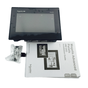
Upgrade or Replace Your HMI
Find compatible HMI panels for discontinued models, machine upgrades, and operator interface replacement.
- New original parts
- Fast response
- Global shipping
When Only One Screen or Tag Fails
If the HMI communicates normally but one value shows an error, the physical network is probably not the first place to look.
Check the affected object for:
- Wrong register or variable address
- Incorrect device/station assignment
- Bit versus word access
- Signed versus unsigned interpretation
- 16-bit, 32-bit, or 64-bit data length
- Byte or word order
- Invalid array index or indirect address
- Address outside the PLC memory range
- Read-only area used for a write command
- Symbol file or tag database that no longer matches the PLC program
Background functions can also generate errors. Review alarms, trend logging, recipes, macros, data sampling, and scripts that continue polling addresses even when the current screen looks normal.
When Communication Is Slow or Intermittent
An intermittent link deserves a different test from a permanent timeout. Record when the fault occurs and what the machine is doing at that moment.
For Serial Networks
- Lower the baud rate temporarily to see whether cable quality or reflections are involved.
- Check termination, biasing, shield continuity, and the Common conductor.
- Look for long branches, loose terminals, or cables moving with the machine.
- Compare failures with drive acceleration, braking, heater switching, and contactor operation.
- Check whether the HMI polling load exceeds what the PLC or serial network can handle.
For Ethernet Networks
- Review managed-switch counters for CRC errors, drops, link changes, and broadcast load.
- Test with one known-good cable and switch.
- Check for duplicate IP addresses and devices that appear only after startup.
- Reduce unnecessary HMI polling, logging, and very short update intervals.
- Review PLC connection limits and whether another client is consuming all available sessions.
- Check firewall, router, and redundant-network event logs at the time of failure.
Long timeouts and repeated retries can make a small problem feel like a frozen HMI. Correct the failed device or invalid tag instead of simply increasing every timeout value.
Build a Minimal Communication Test
When the machine configuration is complex, create the smallest possible working link.
- Connect one HMI to one PLC with a verified cable or isolated switch.
- Use the exact driver listed for that PLC family.
- Configure one serial station or one IP destination.
- Create one numeric display for a known, safe PLC register.
- Create one controlled write test only if machine safety permits it.
- Disable macros, recipes, remote devices, and background polling during the test.
- Confirm stable reads before rebuilding the full project or network.
Choose a test register whose value can be verified in the PLC programming software. Avoid commanding outputs or changing machine-control data simply to prove communication.
This test separates a basic connection problem from an application problem. If the single register works, add devices and background functions gradually until the failing element appears.
After Replacing a PLC, HMI, or Communication Cable
Replacement parts often look identical but differ in port type, firmware, supported protocol, or connector pinout. Check the complete model suffix and installed communication options.
After replacement, verify:
- Correct PLC program and parameters were transferred
- Correct HMI project and runtime version were transferred
- Serial or Ethernet settings are active after restart
- PLC port mode is not left in programming-only or default mode
- HMI driver matches the replacement CPU family
- New station or IP address is not still at its factory default
- Cable pinout matches the replacement model, not only the old connector
- Termination and DIP-switch settings match the device’s position on the network
For discontinued equipment or an urgent breakdown, Kwoco can help compare the full PLC, HMI, communication-module, and cable model numbers before a replacement is ordered. Supplying clear nameplate and port photos is usually faster than identifying a part from the front-panel appearance alone.
When Hardware Is Actually Suspect
Hardware becomes a stronger suspect after settings and wiring have been verified with a known-good comparison.
Warning signs include:
- No Ethernet link on a known-good cable and switch port
- No transmit activity from a port that is correctly configured and actively polling
- A serial port that works only when the connector is held in one position
- Visible contamination, bent pins, heat damage, or failed isolation components
- Communication that returns when either the PLC, HMI, converter, or cable is substituted
- A port that fails the manufacturer’s built-in loopback or interface test
Before declaring a port defective, repeat the test with the minimum configuration and save evidence: project versions, parameters, cable drawing, voltage or continuity results, and the swap test. This avoids replacing an HMI only to reconnect it with the same incorrect cable.
If a verified port, converter, or communication module needs replacement, match the complete model and revision. Kwoco can also help identify compatible PLC, HMI, serial adapter, and industrial Ethernet replacements when the original item is no longer readily available.
Frequently Asked Questions
Ping only shows that the target IP address is reachable and responds to ICMP. The HMI can still fail if it uses the wrong PLC driver, TCP/UDP port, station or route, or if the PLC communication service is disabled. After a successful ping, check the application protocol and PLC-side connection settings.
Do not rely on the letters alone because naming conventions vary. Compare the pin numbers and functional signal names in both product manuals. If all serial settings match but there is no valid receive activity, power down and verify the D+/D-, D1/D0, or transmit/receive polarity against the official wiring diagrams.
No. A passive RS-485 trunk is normally terminated only at its two physical ends, and some devices already contain switchable termination. The actual resistor value and switch arrangement must follow the cable and equipment manuals. Adding termination at every station can overload the network.
Project transfer and PLC runtime communication are separate connections. The HMI may receive a project through USB or Ethernet while the runtime project uses another serial port, another IP address, or a different PLC driver. Check the device assigned inside the HMI project and the physical PLC cable path.
Use an interface supported by both products and suitable for the installation. RS-232 is practical for a short point-to-point link. RS-485 is useful for longer or multidrop serial networks when topology and termination are controlled. Ethernet provides easier integration and richer diagnostics but requires correct IP, protocol, port, and network-security configuration.
Power your projects with brand-new, original Omron, Mitsubishi, Schneider PLC – in stock, ready now!
Printable PLC-HMI Communication Checklist
Use this final pass before escalating the fault.
- [ ] PLC and HMI power and status are normal.
- [ ] Exact product models and port types are confirmed from manuals.
- [ ] The cable follows the official pinout for this device pair.
- [ ] RS-232 TX/RX/common and any required handshake signals are correct.
- [ ] RS-485 two-wire/four-wire mode, polarity, Common, topology, termination, and bias are correct.
- [ ] Serial protocol, baud rate, data bits, parity, stop bits, and station number match.
- [ ] Ethernet link is present and the live IP, mask, gateway, and VLAN are correct.
- [ ] There are no duplicate station numbers or IP addresses.
- [ ] HMI driver, transport, port, PLC family, route, and PLC-side service match.
- [ ] A minimal one-HMI, one-PLC, one-register test has been completed.
- [ ] Failed tags have valid addresses, data types, and access rights.
- [ ] Intermittent faults have been compared with noise sources, network counters, and polling load.
- [ ] Original parameters and test results have been recorded before hardware replacement.
Contact Us
Just fill out your name, email address, and a brief description of your inquiry in this form. We will contact you within 24 hours.
Product Category
Hot Sale Products
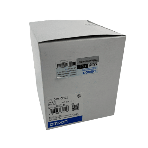
Omron CPU Unit CJ2M-CPU32
Omron PLC CJ1W-PA202 Supplier in China
Mitsubishi MR-JE Series 400w Servo Drive MR-JE-40A
Need a Fast Match?
Share your model or spec and our team will help you find the right fit-fast.
- Expert support
- Quick response
- Competitive price
- +86-755-81481609
- [email protected]
You May Also Find These Topics Interesting
Unraveling the Secrets of Miniature Circuit Breakers (MCBs)
This article delves into the fascinating world of Miniature Circuit Breakers (MCBs), explaining their crucial role in safeguarding electrical systems, exploring their

Top 5 Omron PLC Suppliers in Canada: A Buyer’s Guide
Trying to source industrial automation parts in Canada can feel like trying to get a decent cup of coffee in a gas

Mitsubishi MR-J4 AL.16 vs AL.20: Encoder Communication Faults Explained
An MR-J4 encoder alarm does not automatically mean the motor needs replacing. The amplifier has detected a problem communicating with the encoder;