
Siemens SINAMICS G120 Fault Codes: F0001, F0002, F30001
Table of Contents
With G120 drives, the first diagnostic question is not simply “What does this code mean?” It is “Which Control Unit, Power Module, and firmware version produced it?”
Early G120 systems and later G120-2 systems use different fault-number formats. F0001 and F0002 are widely seen on first-generation G120 Control Units with older firmware, while F30001 and F30002 belong to the later SINAMICS-style power-unit fault structure used by Control Units such as the CU240B-2 and CU240E-2.
This guide explains both formats, shows how to separate motor and wiring problems from parameter or Power Module problems, and gives a practical troubleshooting order for field work.
Scope: Why One G120 May Show F0001 and Another Shows F30001
SINAMICS G120 is a modular drive family. A complete drive may include a Control Unit such as a CU240S, CU240E, CU240B-2, CU240E-2, CU250S-2, or CU230P-2 and a separate Power Module such as a PM240, PM240-2, PM250, or PM230.
The Control Unit and firmware determine how faults are numbered and which parameters, fault values, and reset methods are available.
As a practical rule:
- F0001 and F0002 are associated with the earlier four-digit fault system found on first-generation G120 platforms and older firmware.
- F30001 and F30002 are part of the five-digit power-unit fault system used on G120-2 and related later-generation SINAMICS platforms.
- The underlying electrical problem may be similar, but the detailed causes, supplementary fault values, and diagnostic procedure must come from the manual for the exact Control Unit and firmware.
Before changing any parameter, record the Control Unit order number, Power Module order number, firmware version, motor nameplate, complete displayed code, and any fault value available in r0949.
- Related Product
Need a Replacement Altivar Drive?
Browse new original Altivar drives for maintenance, troubleshooting, and replacement projects.
- New original parts
- Fast response
- Global shipping
Safety Before Troubleshooting a SINAMICS G120
Only qualified personnel should work on the drive system.
Disconnect the line supply on the input side of the inverter, apply the required lockout procedure, and wait at least five minutes for the DC-link capacitors to discharge. Then verify the absence of voltage using an appropriately rated measuring device before touching the line, DC-link, braking, or motor terminals.
An unlit display or stopped fan does not prove that the drive is de-energized.
Never perform an insulation-resistance or high-potential test while the motor cable is connected to the Power Module. Disconnect the cable from the drive and test the motor and cable according to their manufacturers’ instructions.
SINAMICS G120 Fault Code Quick Reference
This table covers common power-section faults related to the three codes in the title. It is not a complete G120 fault list.
| Fault code | Meaning | Typical platform | First checks |
|---|---|---|---|
| F0001 | Overcurrent | Early G120 / older firmware | Output short circuit, ground fault, motor data, ramp time, mechanical load |
| F0002 | DC-link overvoltage | Early G120 / older firmware | Deceleration time, regenerative load, line voltage, braking arrangement |
| F0003 | Undervoltage | Early G120 / older firmware | Input voltage, missing phase, contactor, fuse, voltage dip |
| F0004 | Inverter overtemperature | Early G120 / older firmware | Cooling, fan, ambient temperature, overload, pulse frequency |
| F0005 | Inverter I2t overload | Early G120 / older firmware | Duty cycle, drive sizing, current demand, cooling |
| F30001 | Power unit overcurrent | G120-2 / later firmware | Motor data, star/delta connection, output cable, load, ramp, line quality |
| F30002 | Power unit DC-link overvoltage | G120-2 / later firmware | p1121, line voltage, regenerated energy, Vdc controller settings |
| F30003 | Power unit DC-link undervoltage | G120-2 / later firmware | Input voltage, line phases, upstream switching devices |
| F30004 | Power unit heat-sink overtemperature | G120-2 / later firmware | Fan, airflow, ambient temperature, load, p1800 |
| F30005 | Power unit I2t overload | G120-2 / later firmware | Continuous load, duty cycle, motor and Power Module ratings, p0640 |
| F30011 | Line phase failure in main circuit | G120-2 / later firmware | Main fuses, phase balance, supply distortion, motor feeder |
| F30015 | Motor cable phase failure | G120-2 / later firmware | U/V/W cable, output contactor, motor connection, control stability |
| F30021 | Power unit ground fault | G120-2 / later firmware | Motor cable, motor insulation, brake circuit, current sensing |
| F30022 | Power unit Uce monitoring | Some Power Modules | Output short circuit, power semiconductor or gate-supply problem |
F0001: Overcurrent on an Early SINAMICS G120
F0001 means the inverter detected an overcurrent condition. On early G120 systems, this is generally a hard protective trip rather than a normal indication that the drive has reached the adjustable current limit.
Common causes include:
- A phase-to-phase short circuit in the motor cable or motor
- A ground fault in the motor cable or winding
- A damaged Power Module output stage
- Incorrect motor data or excessive voltage boost
- A ramp-up time that is too short
- A motor or mechanical load that is too large for the drive
- Connecting to a motor that is already rotating without suitable flying-restart configuration
What to check first for F0001
Start with the moment when the trip occurs.
If F0001 appears immediately when the run command is enabled, suspect an output short circuit, ground fault, incorrect star/delta connection, a rotating motor, excessive voltage boost, or a damaged power stage.
If it occurs during acceleration, check ramp-up time p1120, motor nameplate data, current demand, breakaway torque, and mechanical binding.
If it occurs only at high speed or heavy load, compare actual current with the motor and drive ratings. Inspect the driven machine for a process change, blocked filter, seized bearing, jammed conveyor, pump restriction, or another source of excess torque.
Do not treat p0640 as a cure for F0001. The current-limit controller can reduce output frequency to control current, but a hard overcurrent trip indicates that the protective threshold has still been exceeded.
F0002: DC-Link Overvoltage on an Early SINAMICS G120
F0002 means the DC-link voltage rose beyond the permitted threshold.
The most common field scenario is rapid deceleration. When a high-inertia or overhauling load drives the motor faster than the commanded electrical speed, the motor regenerates energy into the inverter. That energy raises the DC-link voltage.
Other causes include excessive line voltage, an incorrectly entered line-supply voltage, an unsuitable Vdc controller configuration, or a braking arrangement that cannot absorb the regenerated energy.
How to fix F0002
- Increase ramp-down time p1121 and retest under controlled conditions.
- Check whether the load is regenerative, especially on centrifuges, large fans, unwinders, hoists, and descending conveyors.
- Measure the incoming line voltage and compare it with the drive and Power Module ratings.
- Review the configured line voltage p0210 and the applicable DC-link voltage controller settings.
- Verify whether the installed Power Module supports an internal or external braking resistor and whether the resistor and duty cycle are correctly selected.
Do not add a braking resistor based only on the G120 family name. PM230, PM240, PM240-2, and PM250 modules do not all manage regenerated energy in the same way. Use the hardware manual for the exact Power Module.
- PLC Solutions
Find the Right PLC for Your System
Explore new original PLC CPUs, I/O modules, power supplies, and communication units for maintenance and automation projects.
- New original parts
- Fast response
- Global shipping
F30001: Power Unit Overcurrent on a G120-2
F30001 means the Power Module detected an overcurrent condition. Siemens assigns an OFF2 reaction, which removes the inverter pulses and allows the motor to coast unless the machine provides another stopping mechanism.
The Siemens CU240B-2/CU240E-2 List Manual identifies the following possible causes:
- Incorrect closed-loop control parameterization
- Motor short circuit or ground fault
- Ramp-up time too short in U/f operation
- Motor rated current much greater than the Power Module rating in U/f operation
- High discharge or recharge current during a line interruption or DC-link dip
- Missing or incorrectly connected line reactor where one is required
- Incorrect power-cable connection
- Motor cable longer than permitted for the configuration
- Defective Power Module
- Interrupted line phase
That list is useful because it prevents a common mistake: assuming every F30001 means failed IGBTs. The Power Module is one possible cause, but the motor circuit, commissioning data, load, supply, and installation must be checked first.
Use r0949 to Narrow Down F30001
On later G120 Control Units, r0949 stores supplementary information for the fault. For F30001, Siemens defines the fault value bitwise:
| r0949 bit | Indication |
|---|---|
| Bit 0 | Overcurrent detected in phase U |
| Bit 1 | Overcurrent detected in phase V |
| Bit 2 | Overcurrent detected in phase W |
| Bit 3 | Overcurrent detected in the DC link |
A value of zero means the drive did not identify a specific overcurrent phase.
Read r0949 before clearing the fault history. A repeated indication on one output phase supports a focused check of that phase’s cable, motor winding, terminal, and power stage. A DC-link indication points the investigation toward supply disturbances, recharge current, or the internal power section.
The fault value is evidence, not a final verdict. It should be considered together with the fault time, operating state, actual current, and what the machine was doing when the trip occurred.
F0001 vs. F30001: Are They the Same Fault?
They describe the same broad fault category, but they are not interchangeable fault records.
| Point | F0001 | F30001 |
|---|---|---|
| Code system | Early four-digit format | Later five-digit SINAMICS format |
| Common context | First-generation G120 and older firmware | G120-2 and later Control Units |
| Meaning | Inverter overcurrent | Power unit overcurrent |
| Supplementary diagnosis | Depends on older CU and parameter manual | r0949 can identify U, V, W, or DC-link involvement |
| Manual to use | Manual matching the early Control Unit and firmware | List Manual matching the exact G120-2 Control Unit |
The right approach is to identify the installed hardware and use its own List Manual. Do not enter a five-digit code into an old four-digit troubleshooting chart or assume that every legacy remedy applies unchanged to a newer Power Module.
F30002: The Later Equivalent Overvoltage Category
On a later G120-2 system, F30002 indicates Power Module DC-link overvoltage. The usual causes are regenerated motor energy, excessive line voltage, a missing line phase, disabled DC-link voltage control, or unsuitable Vdc controller dynamics.
The first practical adjustment is normally to increase ramp-down time p1121. Siemens also points to rounding times p1130 and p1136, the relevant Vdc controller configuration, line-voltage setting p0210, and line-phase checks.
For F30002, r0949 records the DC-link voltage at the trip in 0.1 V units. That value is particularly useful when deciding whether the problem follows a deceleration event or an unstable/high incoming supply.
Other Related G120 Faults Worth Separating
F30003: DC-Link Undervoltage
Check the line voltage, all supply phases, upstream fuses and contactors, and voltage sag under load. A healthy no-load voltage reading does not rule out a weak connection that collapses when current rises.
F30004: Heat-Sink Overtemperature
Check fan operation, air paths, cabinet temperature, contamination, motor load, and pulse frequency. The fault cannot be successfully acknowledged until the temperature has fallen below the applicable threshold.
F30005: Power Unit I2t Overload
This fault indicates that the Power Module has been overloaded over time, rather than experiencing the instantaneous current event represented by F30001. Review continuous load, duty cycle, drive sizing, motor rating, and current limit p0640.
F30021: Ground Fault
Treat this as an insulation and wiring problem until testing proves otherwise. Disconnect the motor circuit from the Power Module before insulation testing. Check the motor cable, motor winding, cable glands, junction box, brake connection, and grounding system.
F30022: Power Semiconductor Monitoring
This fault can be caused by an output short circuit or a defective semiconductor or gate-supply circuit. It is more likely to require Power Module service, but the output cable and motor must still be isolated and checked before replacement.
- HMI Replacement
Upgrade or Replace Your HMI
Find compatible HMI panels for discontinued models, machine upgrades, and operator interface replacement.
- New original parts
- Fast response
- Global shipping
Diagnose the Fault by When It Happens
The operating stage often narrows the search faster than the code alone.
| When the trip occurs | More likely causes |
|---|---|
| At power-up, before a run command | Power Module fault, supply problem, internal precharge or measurement issue |
| Immediately at pulse enable | Output short/ground fault, incorrect motor connection, rotating motor, defective power stage |
| During acceleration | p1120 too short, excessive load inertia, incorrect motor data, mechanical binding |
| At constant speed | Process overload, unstable control, cable/insulation breakdown, missing phase, undersized drive |
| During deceleration | Regenerative energy, p1121 too short, high line voltage, insufficient braking capacity |
| After long operation | Thermal loading, fan or airflow problem, duty-cycle mismatch, intermittent insulation fault |
A Practical Troubleshooting Sequence
Step 1: Preserve the Evidence
Record the complete fault code, Control Unit and Power Module order numbers, firmware, motor data, operating stage, load condition, and recent machine changes.
Read the fault buffer before resetting it. Depending on the Control Unit and firmware, useful parameters include r0945 or r0947 for the fault number, r0948 for fault time, and r0949 for the supplementary fault value.
Step 2: Check the Machine
Confirm that the motor shaft and driven equipment can move as expected. Inspect bearings, couplings, gearboxes, belts, pumps, fans, conveyors, and process restrictions.
Step 3: Isolate and Inspect the Motor Circuit
After lockout and DC-link discharge, inspect U, V, and W terminals, output contactors, cable routing, shields, glands, junction boxes, and motor connections.
Disconnect the motor cable from the Power Module before resistance or insulation testing. Test the cable and motor separately so a failure can be located rather than merely confirmed.
Step 4: Verify Commissioning Data
Compare the motor nameplate with parameters such as rated voltage p0304, rated current p0305, rated power p0307, rated frequency p0310, and rated speed p0311. Confirm the motor star/delta connection matches the applied voltage.
Review control mode p1300, ramp-up time p1120, ramp-down time p1121, and current limit p0640. If the motor or Power Module was replaced, confirm that commissioning and motor identification were completed as required.
Step 5: Check the Supply and Installation
Measure all input phases and look for imbalance or a voltage dip at the instant of the trip. Inspect fuses, contactors, terminals, transformer loading, and line-reactor installation.
Confirm that the motor cable type and length are permitted for the Power Module, pulse frequency, output reactor, and EMC arrangement.
Step 6: Reset Only After Correcting the Cause
The word IMMEDIATELY in the Siemens acknowledgement field means the fault belongs to the immediate-acknowledgement category. It does not mean the drive should be reset immediately without investigation.
Remove the run command, make the machine safe, correct the cause, then acknowledge the fault through the configured operator panel, digital input, or control system. If the same power fault returns, stop repeated reset attempts.
Automatic restart can cause the motor to start when the fault disappears or power returns. Use it only after a machine-level risk assessment and with suitable safeguards.
Frequently Asked Questions
They represent the same broad overcurrent category, but they belong to different G120 code generations. F0001 is typical of earlier G120 systems, while F30001 is the later power-unit overcurrent code. Use the List Manual for the exact Control Unit and firmware.
The motor is probably regenerating too much energy into the DC link during deceleration. Increase p1121, check line voltage and load inertia, then verify the Vdc controller and braking arrangement supported by the exact Power Module.
For F30001, r0949 indicates whether overcurrent was detected in phase U, V, W, or the DC link. Bits 0, 1, 2, and 3 correspond to those locations, while zero means no specific phase was identified.
Only after the cause has been identified or a controlled inspection shows it is no longer present. A single acknowledged trip may allow testing, but repeated F30001 resets can expose the motor, cable, and Power Module to further damage and should be stopped.
Not necessarily. Siemens also lists incorrect control parameters, motor short or ground fault, short acceleration time, incorrect motor/drive sizing, line problems, cable issues, and missing reactor conditions. Replace the Power Module only after these external causes have been checked.
Power your projects with brand-new, original Omron, Mitsubishi, Schneider Servo – in stock, ready now!
When Does the Power Module Need Replacement?
Replacement becomes reasonable when qualified testing has confirmed the motor, cable, load, supply, connection, and commissioning data are correct, yet the fault remains or returns under controlled conditions.
A fault that appears before the motor is enabled, persists after the external power circuit has been safely isolated and verified, or changes to F30022 or another internal power-stage code strengthens the case for Power Module service or replacement.
Do not select a replacement by kW alone. Match the complete Power Module and Control Unit order numbers, input voltage, rated current, overload duty, frame size, braking method, communication interface, safety functions, firmware compatibility, memory-card requirements, and parameter backup.
Kwoco can help with G120 replacement identification when the original modular combination is unclear. Send clear photos of the Control Unit and Power Module nameplates, the motor nameplate, the full fault and r0949 value, cabinet layout, firmware information, and a STARTER or Startdrive parameter backup where available.
Official Siemens References
Contact Us
Just fill out your name, email address, and a brief description of your inquiry in this form. We will contact you within 24 hours.
Product Category
Hot Sale Products
Omron CPU Unit CJ2M-CPU32
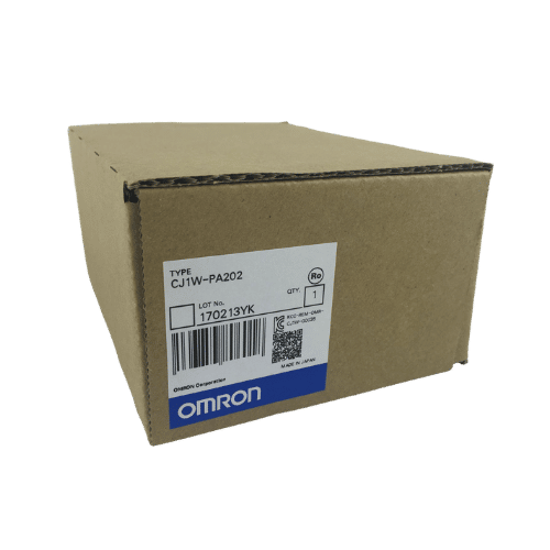
Omron PLC CJ1W-PA202 Supplier in China
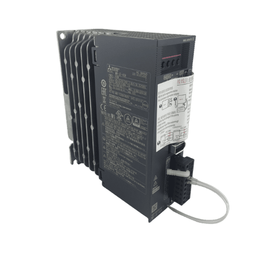
Mitsubishi MR-JE Series 400w Servo Drive MR-JE-40A
Need a Fast Match?
Share your model or spec and our team will help you find the right fit-fast.
- Expert support
- Quick response
- Competitive price
- +86-755-81481609
- [email protected]
You May Also Find These Topics Interesting
Omron PLC Buying Guide for US Buyers
If you source automation parts in the US, Omron is probably not a new name to you. What usually takes time is
10 Essential Insights About OMRON PLC CJ2 Series
10 Essential Insights About OMRON PLC CJ2 Series KWOCO focuses in internationally renowned industrial automation products, I’ve had extensive hands-on experience with
Understanding PLCs: Uses of Programmable Logic Controllers
Programmable Logic Controllers (PLCs) have become an integral part of modern industrial automation. If you’ve ever wondered how complex machinery and production