Is Relay Output Digital or Analog? Understanding the Basics
Relays are often referred to as “automatic switches,” as they control larger circuits or loads using smaller control currents. The core working principle of a relay involves electromagnetic induction to change the state of the contacts, thereby controlling the circuit.
This operation corresponds to binary logic: either “on” or “off,” which is why it is considered a typical digital signal output. The nature of a digital signal is discrete, meaning it has only two states. Relays use these two states (on or off) to control circuits.
Table of Contents
As an engineer at Kwoco, I frequently work with different types of relays. Whether in PLC control systems or large-scale industrial automation projects, relays play a crucial role. They ensure electrical isolation between circuits and control complex high-voltage circuits using simple low-voltage signals.
What Are the Practical Applications of Relay?
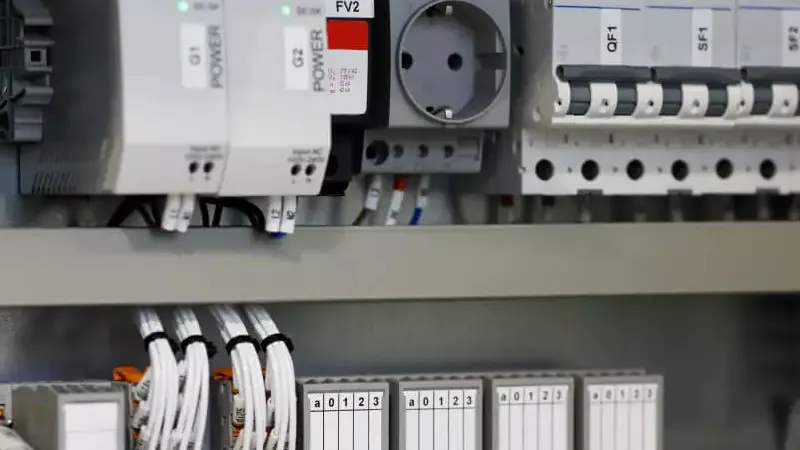
Relays are widely used in control panels, building automation, and manufacturing automation. Their role is particularly evident in situations requiring remote control or automatic switching.
With relays, low-power signals can easily control high-power devices, such as motors, lighting, and even heating equipment. This technology improves system safety and significantly reduces the need for manual intervention.
Types of Relay
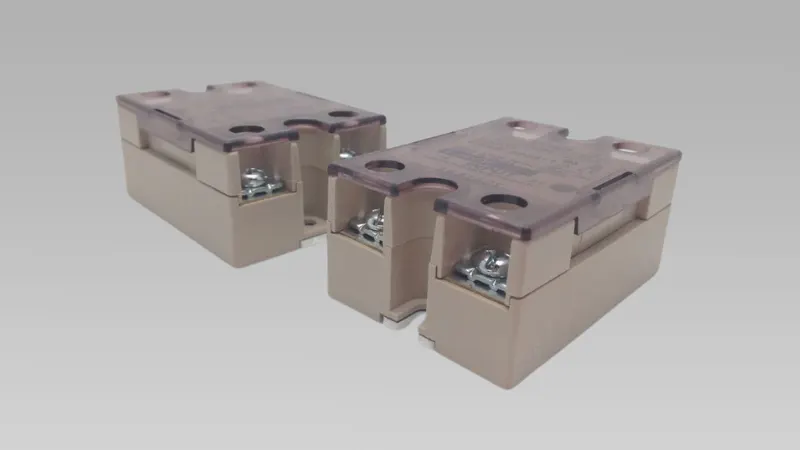
Relays generally fall into two main categories: Electromechanical Relays and Solid-State Relays.
1. Electromechanical Relays (EMR)
Electromechanical relays control circuits by using an electromagnetic coil. Their basic components include the coil, contacts, armature, and spring. Here are the key features:
- Working Principle: When the coil is energized, a magnetic field attracts the armature, causing the contacts to move and either complete or break the circuit. This physical movement results in mechanical contact switching.
- Advantages: Due to their mechanical action, they can handle higher currents and voltages, making them widely used in power systems, heavy equipment control, and industrial automation.
- Disadvantages: The presence of mechanical components makes them more prone to wear, and their response speed is slower, especially in high-frequency switching scenarios.
- Applications: Commonly used for motor starting, industrial automation systems, household appliances, and power management systems.
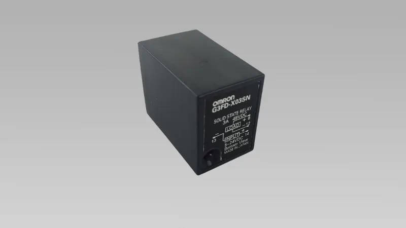
2. Solid-State Relays (SSR)
Solid-state relays differ from electromechanical relays in that they have no moving parts and rely entirely on electronic components for switching. Internally, they consist of components such as optocouplers and semiconductor devices like thyristors or triacs.
- Working Principle: Solid-state relays use an optocoupler to isolate and transmit control signals. When an LED in the control circuit lights up, the optocoupler receives the optical signal and triggers semiconductor devices to conduct or interrupt the load circuit.
- Advantages: Since there are no mechanical parts, solid-state relays have faster response times, and they do not suffer from wear, giving them a longer lifespan. They also operate more quietly and perform well in high-frequency switching applications.
- Disadvantages: Solid-state relays typically have lower current and voltage capacities than electromechanical relays, and they are generally more expensive.
- Applications: Commonly used in high-frequency switching, electronic device control, temperature control systems, and industrial automation equipment.
Factors to Consider When Choosing a Relay
Both electromechanical relays and solid-state relays have their pros and cons. When choosing a relay, consider the needs of the specific application, such as switching frequency, load size, and cost.
Electromechanical relays are better suited for high-current, high-voltage applications, while solid-state relays are ideal for high-frequency, low-noise, and long-life applications.
Connection of Relay in Electrical Circuits
Relays in electrical systems act like switches, controlling high-voltage or high-current circuits through low-voltage or low-current control circuits. There are several common relay contact configurations:
- Normally Open (NO): The contacts are open when the relay is inactive. When the coil is energized, the contacts close, completing the circuit. This configuration is used where the circuit needs to be activated under specific conditions.
- Normally Closed (NC): The contacts are closed when the relay is inactive. When the relay is energized, the contacts open, breaking the circuit. This configuration is used where the circuit needs to be deactivated under certain conditions.
- Double Throw (DT): Also known as double-throw contacts, this configuration can switch between normally open and normally closed states. When the relay is energized, the connection changes from normally closed to normally open.
Relay contact configurations not only determine the circuit’s on-off state but also allow for multi-circuit switching through designs like Single Pole Single Throw (SPST), Single Pole Double Throw (SPDT), Double Pole Single Throw (DPST), and Double Pole Double Throw (DPDT), which can be selected based on the application.
Relay Outputs
Relay output signals are typically categorized as either digital or analog, but in most cases, relay output is considered digital (i.e., a switching signal that represents on or off, 0 or 1). This is because a relay functions as a switch, controlling the circuit’s state, which is a characteristic of digital signals. In PLC systems, relays are commonly used to control loads such as solenoids, lights, and small motors.
Regarding relay output configurations, there are three common types:
- Form A (Normally Open): When the relay coil is energized, the contacts close, and the circuit is completed.
- Form B (Normally Closed): When the relay coil is not energized, the contacts remain closed, and the circuit is completed. Energizing the coil opens the circuit.
- Form C (Changeover Contacts): This configuration includes both normally open and normally closed contacts, allowing switching between the two states.
In PLC systems, relay outputs are used to control external loads and protect the control circuit from high voltage spikes or other electrical interference through electrical isolation.
Are Relay Working Principles Complex?
Relay working principles are quite simple, especially for electromechanical relays. When the control circuit is energized, the electromagnetic coil creates a magnetic field, which moves mechanical parts such as the armature, opening or closing the relay contacts to control the circuit.
This process is based on electromagnetic force, making mechanical movement central to electromechanical relays.
For solid-state relays (SSR), no mechanical parts are involved. Instead, they rely on electronic components for switching operations. They use an LED to generate an optical signal, which is transmitted via an optocoupler to trigger the control circuit. Solid-state relays perform well in high-frequency switching environments, as they have no mechanical wear and tear.
Thus, while both electromechanical and solid-state relays are simple in their core operation, they differ in the way they control circuits: electromechanical relays rely on mechanical movement, while solid-state relays depend on electronic components.
What Is the Relationship Between Relay and PLCs?
In a PLC (Programmable Logic Controller) system, relays are often used to control small-to-medium load switching operations, such as controlling solenoids, lights, and small motors. Relays, combined with PLCs, ensure system stability and safety.
The PLC sends instructions to control the relay’s on/off state, allowing for automated load control. In such systems, relays play an important role in providing electrical isolation and load driving, especially when larger loads are involved. A PLC can use an intermediary relay to handle these loads efficiently.
Additionally, PLC-controlled relays enhance system flexibility and ensure high reliability, making them suitable for complex industrial environments.
Frequently Asked Questions About Relay
1. Why Does My Relay Get Hot?
Relay overheating can be caused by several factors. First, if the relay operates under high load conditions for extended periods, the contacts may produce an arc, which generates heat. Second, the current drawn by the coil during operation can generate heat, especially in high-voltage or high-current conditions.
Lastly, poor heat dissipation or high ambient temperatures can contribute to heat buildup. If the relay frequently overheats, check if the load exceeds the relay’s rated specifications or consider upgrading to a higher-capacity relay.
2. What Is the Difference in Lifespan Between Electromechanical and Solid-State Relays?
The lifespan of an electromechanical relay is mainly affected by wear and tear on its mechanical components, such as contacts and the armature, especially under high-current or high-voltage conditions. Solid-state relays, on the other hand, have no moving parts and rely on electronic components for switching, resulting in a longer lifespan, particularly in applications involving frequent switching. Solid-state relays also perform better in high-frequency applications and typically outlast electromechanical relays.
3. When Should I Choose a Solid-State Relay?
If your application requires frequent switching or has high demands for fast response times, a solid-state relay is the better choice. It is especially suited for high-frequency switching, noise-free operation, and high-temperature environments.
Additionally, solid-state relays perform better in explosion-proof environments and long-life industrial applications. If durability, low maintenance, and high efficiency are important for your system, a solid-state relay is likely more suitable.
4. Can relays achieve complete isolation between circuits?
Yes, one of the designs of relays is to achieve electrical isolation. Whether it is an electromechanical relay or a solid-state relay, they can ensure safety by isolating the control circuit and the load circuit.
This isolation avoids the low-voltage control circuit from directly contacting the high-voltage load, preventing the high voltage from flowing back into the control loop, thereby protecting the system from damage.
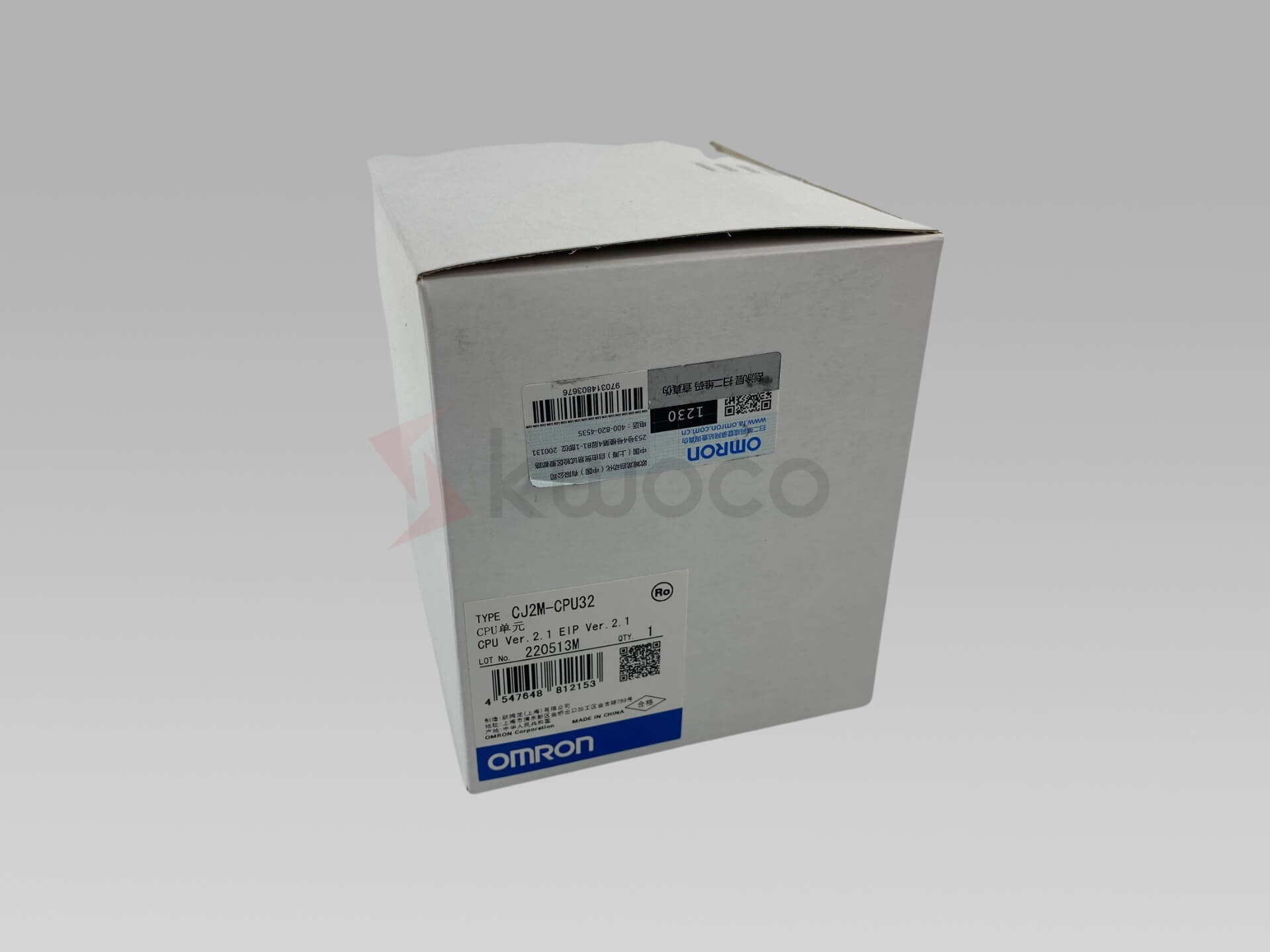
Power your projects with brand-new, original Omron, Mitsubishi, Schneider PLC – in stock, ready now!
Conclusion
The output of relays is usually digital signals, and they play a key role in industrial control systems. Whether it is traditional electromechanical relays or modern solid-state relays, they are widely used in different application scenarios. Choosing the right relay type is crucial to the stability of your system, remember to make a choice based on your actual needs.
Looking for new, original PLCs for your projects? At Kwoco, we stock the latest PLCs from top brands like Omron, Mitsubishi, and Schneider. Shop with confidence—fast shipping, guaranteed quality! Buy Now
Contact Us
Just fill out your name, email address, and a brief description of your inquiry in this form. We will contact you within 24 hours.
You May Also Find These Topics Interesting
PLC Programming Guide: Master Industrial Automation
Are you looking to understand the world of Programmable Logic Controllers (PLCs) and how they revolutionize industrial automation? This comprehensive guide will walk you through everything you need to know about PLC programming, from basic concepts to advanced techniques, helping both beginners and experienced professionals enhance their automation skills.

Allen-Bradley vs ABB: Which Is Best for Industrial Automation?
In the fast-evolving world of industrial automation, two names often stand out: Allen-Bradley and ABB. Both are giants in the industry, offering cutting-edge solutions like PLCs, VFDs, and controllers. But are they the same? This article delves into the intricacies of these two brands, comparing their offerings to help you make informed decisions for your control systems.

Top 5 Omron PLC Suppliers in Canada: A Buyer’s Guide
Trying to source industrial automation parts in Canada can feel like trying to get a decent cup of coffee in a gas station at 3 AM. It’s frustrating. It’s often disappointing. And it usually costs more than it should.
I’ve been in this game for over ten years. I’ve written specs, I’ve managed retrofits, and I’ve pulled my hair out waiting for a “local” distributor to return a phone call.

