CNC Machine Mastery: Understanding the Crucial Difference Between Feed Rate and Spindle Speed
Table of Contents
1. What is Cutting Speed in CNC Machining?
Cutting speed is a fundamental concept in CNC machining, representing the surface speed at which the cutting tool moves past the workpiece. It’s typically measured in surface feet per minute (SFM) or meters per minute. Essentially, cutting speed is the speed at which the cutting edge of the tool traverses the material being cut.
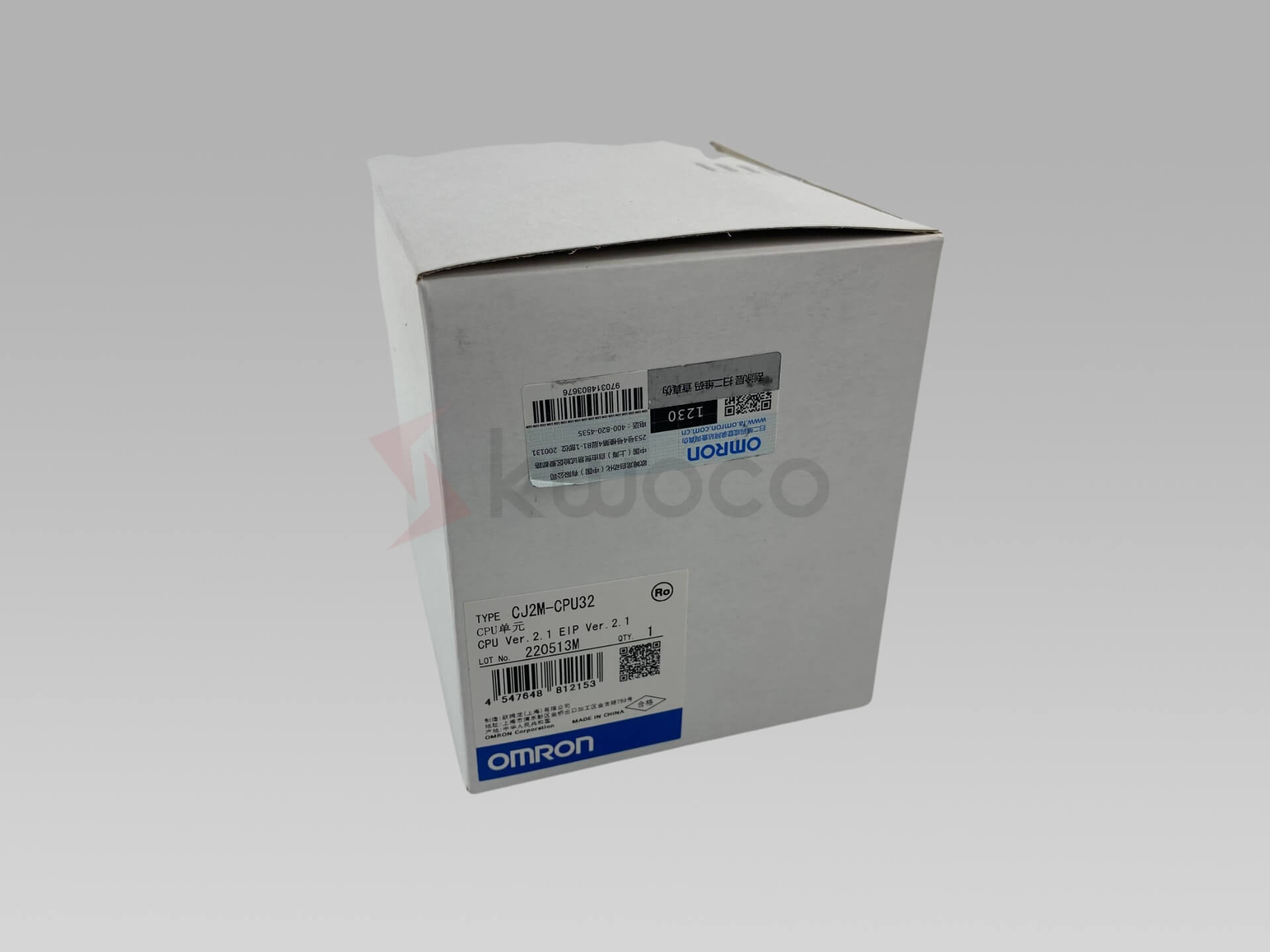
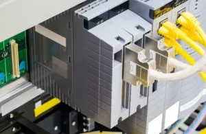
This parameter is vital as it directly influences the efficiency of the cutting process and the quality of the finished surface. One example of a component that plays a role in cutting speed is Omron PLC.
These PLCs can control the speed of various components in a CNC machine, ensuring consistent and precise cutting. You can find more about this and other products on the Omron PLC page.
Imagine a lathe operation where a cylindrical workpiece is being turned. The cutting speed would be the velocity at which the cutting tool moves along the workpiece’s circumference during one revolution of the spindle.
The calculation involves the diameter of the workpiece and the spindle’s rotational speed (RPM). High cutting speeds can lead to faster material removal but may also cause increased tool wear.
Therefore, choosing the optimum cutting speed is a balance between productivity and tool longevity. The machine’s capabilities, tool material, and the workpiece material all play a crucial role in determining the appropriate cutting speed.
![]()
2. How is Spindle Speed Different from Cutting Speed?
While often used interchangeably, spindle speed and cutting speed are distinct yet interconnected concepts. Spindle speed refers to the rotational speed of the machine’s spindle, measured in revolutions per minute (RPM).
It’s the speed at which the spindle – which holds either the workpiece (in a lathe) or the cutting tool (in a mill) – rotates. On the other hand, cutting speed, as previously defined, is the surface speed of the cutting tool relative to the workpiece.
The relationship between cutting speed and spindle speed can be visualized as a simple formula: Spindle Speed (RPM) = (Cutting Speed (SFM) * 3.82) / Tool Diameter.
This formula highlights that for a given cutting speed, the spindle speed must be adjusted based on the diameter of the cutting tool or workpiece. For instance, a smaller tool diameter requires a higher spindle speed to achieve the same cutting speed as a larger tool.
A deep understanding the difference is crucial for CNC programmers and machinists to ensure precise machining. If you’re curious about different CNC tools and how they relate to spindle speed, exploring resources like Mitsubishi PLC can provide valuable insights.
3. What Exactly is Feed Rate in CNC Machining?
Feed rate in CNC machining is the speed at which the cutting tool or workpiece moves relative to each other along a specified axis during the cutting process. In simpler terms, it’s how fast the tool moves through the material being cut.
Feed rate is typically measured in units of distance per revolution (e.g., inches per revolution) or distance per minute (e.g., inches per minute). It’s a critical parameter that affects the chip load on the tool.
For example, in a milling operation, the feed rate determines how quickly the cutter advances into the workpiece for each revolution of the spindle. In a lathe operation, it dictates how much the tool moves along the length of the workpiece during each spindle revolution.
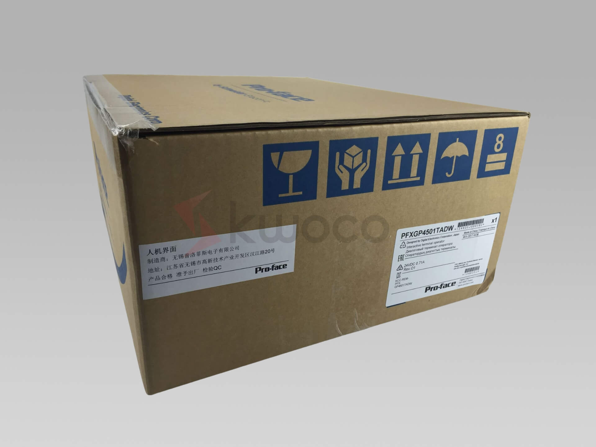
The feed rate must be carefully selected based on the tool material, workpiece material, depth of cut, and desired surface finish. An incorrectly chosen feed rate can lead to issues such as poor surface quality, tool breakage, or excessive tool wear. Learn about HMI, a component that plays an essential role in controlling feed rates, on the HMI page.
![]()
4. How Does Feed Rate Impact the Machining Process?
The feed rate has a profound impact on various aspects of the machining process, including tool life, surface finish, chip formation, and overall machining efficiency. A higher feed rate generally means faster material removal, leading to increased productivity.
However, it also results in a higher chip load, which is the thickness of the material removed by each cutting edge of the tool in one revolution. This can lead to increased cutting forces and heat generation, potentially causing accelerated tool wear or even tool breakage if not managed properly.
Conversely, a lower feed rate reduces the chip load, leading to a better surface finish and potentially longer tool life. However, it also decreases the material removal rate, resulting in longer cycle times and reduced productivity.
Finding the optimum feed rate is a delicate balancing act that requires careful consideration of the specific machining operation, tool material, workpiece material, and desired outcome. Machinists and CNC programmers often refer to feeds and speeds charts and use their experience to determine the appropriate feed rate for a given task.
A Schneider PLC is one example of a system that can be programmed to adjust feed rates dynamically, optimizing the machining process. You can see the full range of products here Schneider PLC.
5. What is the Relationship Between Cutting Speed and Feed Rate?
Cutting speed and feed rate are intertwined parameters that must be considered together to optimize the CNC machining process. They have a direct impact on each other and collectively determine the chip load, material removal rate, tool life, and surface finish. Understanding this relationship is crucial for any machinist or CNC programmer.
| Parameter | Relationship with Cutting Speed | Relationship with Feed Rate |
|---|---|---|
| Chip Load | Increases with lower cutting speed (at constant feed rate) | Increases with higher feed rate (at constant cutting speed) |
| Material Removal Rate | Increases with higher cutting speed | Increases with higher feed rate |
| Tool Life | Generally decreases with higher cutting speed | Can decrease with excessively high or low feed rate |
| Surface Finish | Can be affected by both cutting speed and feed rate | Generally improves with lower feed rate (at constant speed) |
| Cutting Forces | Generally increase with higher cutting speed and feed rate | Generally increase with higher feed rate |
| Heat Generation | Increases with higher cutting speed and feed rate | Increases with higher feed rate |
| Machining Time | Decreases with higher cutting speed and feed rate | Decreases with higher feed rate |
| Spindle Load | Increases with higher cutting speed (at constant feed rate) | Increases with higher feed rate (at constant speed) |
| Machine Power | Directly proportional to cutting speed and feed rate | Directly proportional to feed rate |
| Cutter Deflection | Can increase with higher feed rate, especially with small cutters | Increases with higher feed rate |
In essence, increasing the cutting speed while keeping the feed rate constant results in a smaller chip load but higher material removal. Conversely, increasing the feed rate while maintaining the cutting speed results in a larger chip load and also higher material removal.
The machinist must find the right balance between these two parameters to achieve the desired results without compromising tool life or surface quality. For instance, using a Proface HMI can allow operators to monitor and adjust these parameters in real-time, ensuring optimal performance. Explore more about these HMIs here Proface HMI.
6. How Do You Calculate Optimal Cutting Speed and Feed Rate?
Calculating the optimum cutting speed and feed rate involves a combination of theoretical calculations, empirical data, and practical experience.
Manufacturers of cutting tools often provide recommended cutting parameters (cutting speed and feed per tooth) for their tools based on the workpiece material and tool material. These recommendations serve as a good starting point for determining the initial settings.
The basic formula for calculating spindle speed (RPM) based on cutting speed (SFM) and tool diameter is:
RPM = (Cutting Speed (SFM) * 3.82) / Tool Diameter
Once the spindle speed is determined, the feed rate can be calculated using the feed per tooth and the number of teeth on the cutter:
Feed Rate (IPM) = RPM * Number of Teeth * Feed per Tooth
However, these calculations provide only a starting point. The actual optimum cutting speed and feed rate may vary depending on factors such as machine rigidity, depth of cut (axial and radial depth), tool wear, and desired surface finish.
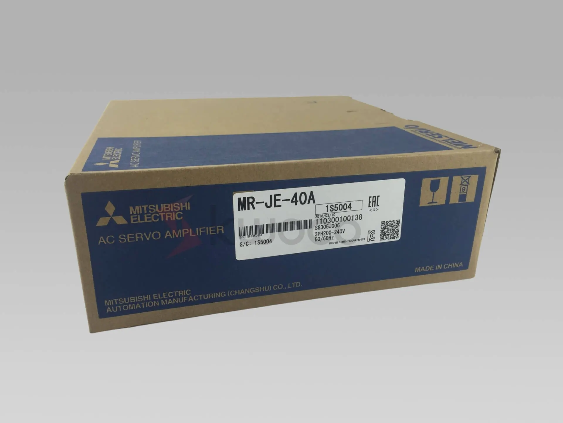
Experienced machinists often fine-tune these parameters based on their observations of the cutting process, such as chip formation, cutting forces, and tool condition. If you need more advanced control, exploring options like Servo systems can provide the precision needed for fine-tuning these parameters.
![]()
7. Why are Spindle Speed and Feed Rate Crucial for Tool Life?
Spindle speed and feed rate are paramount in determining tool life. Incorrectly set parameters can lead to premature tool wear, tool breakage, or even damage to the machine tool itself. Understanding how these parameters affect tool life is essential for cost-effective and efficient machining.
Excessively high cutting speeds can generate excessive heat, leading to rapid tool wear, especially at the cutting edge of the tool. This is because the relative velocity between the cutting tool and the workpiece is high, causing increased friction.
On the other hand, feed rate that are too high can result in excessive chip loads, leading to chipping or breakage of the cutting edge. Conversely, feed rate that are too low can cause rubbing instead of cutting, leading to heat buildup and tool wear.
8. How Do Different Materials Affect Cutting Speed and Feed Rate?
The material being machined significantly influences the choice of cutting speed and feed rate. Different materials exhibit varying degrees of hardness, toughness, and abrasiveness, which directly impact the cutting process.
For instance, softer materials like aluminum can generally be machined at higher cutting speeds and feed rate compared to harder materials like stainless steel.
This is because softer materials generate less heat and cutting forces during machining. Harder materials, on the other hand, require lower cutting speeds to prevent excessive heat buildup and tool wear.
Here’s a simplified chart illustrating recommended cutting speeds (SFM) for various materials using high-speed steel tools:
| Material | Cutting Speed (SFM) |
|---|---|
| Aluminum | 300-1000 |
| Brass | 200-500 |
| Mild Steel | 80-150 |
| Stainless Steel | 40-80 |
| Titanium | 30-60 |
| Cast Iron | 60-120 |
| Plastics | 100-300 |
| Copper | 150-400 |
| Bronze | 100-250 |
| Hardened Steel | 20-40 |
| Nickel Alloys | 25-50 |
| Composites | 50-150 |
| Wood | 500-1500 |
| Acrylic | 200-600 |
| Polycarbonate | 150-450 |
Feed rate are also material-dependent. Tougher materials may require lower feed per tooth to prevent tool breakage, while softer materials can tolerate higher feed per tooth.
9. What are Common Mistakes in Setting Feed and Speed Parameters?
Several common mistakes can occur when setting feed and speed parameters in CNC machining. One prevalent error is relying solely on theoretical calculations without considering the specific machine, tool, and workpiece characteristics. This can lead to suboptimal cutting conditions and reduced efficiency.
Another common mistake is neglecting the machine’s top speed and power limitations. Attempting to run a machine at speeds and feeds beyond its capabilities can result in poor performance, tool damage, or even machine damage.
Additionally, ignoring the tool manufacturer’s recommendations for cutting parameters can lead to premature tool failure.
Failing to adjust feed and speed based on the depth of cut is another frequent error. A deeper cut generally requires a reduction in both cutting speed and feed rate to maintain tool life and prevent tool breakage.
Lastly, not monitoring the cutting process and making necessary adjustments can lead to inefficiencies. Experienced machinists constantly observe factors like chip formation, cutting forces, and surface finish to fine-tune the parameters during operation.
10. What Advanced Techniques Can Optimize CNC Machining Efficiency?
Several advanced techniques can further optimize CNC machining efficiency beyond the basic principles of cutting speed and feed rate. One such technique is constant surface speed (CSS) control, particularly useful in lathe operations.
CSS automatically adjusts the spindle speed (RPM) as the tool moves across different diameters of the workpiece, maintaining a consistent cutting speed. This ensures uniform tool wear and surface finish across the entire workpiece.
High-speed machining (HSM) is another advanced technique that utilizes high spindle speeds, high feed rates, and small depths of cut to achieve high material removal rates while maintaining excellent surface finish and accuracy. HSM requires rigid machines, specialized cutting tools, and advanced CNC programming techniques.
Adaptive control is a cutting-edge technology that uses sensors to monitor the cutting process in real-time and automatically adjust feed and speed parameters to optimize performance. This can compensate for variations in material hardness, tool wear, and other factors that can affect the machining process.
Frequently Asked Questions
Cutting speed refers to the surface speed at which the cutting tool moves past the workpiece, typically measured in surface feet per minute (SFM) or meters per minute. Spindle speed, on the other hand, is the rotational speed of the machine’s spindle in revolutions per minute (RPM).
Feed rate directly influences chip load. A higher feed rate results in a larger chip load, meaning each cutting edge of the tool removes a thicker chip of material per revolution. Conversely, a lower feed rate reduces the chip load.
Cutting speed and feed rate are interdependent parameters that collectively determine the material removal rate, tool life, surface finish, and overall efficiency of the machining process. They must be considered together to achieve optimal results.
Excessively high cutting speeds can generate excessive heat, leading to rapid tool wear, tool deformation, or even tool failure. It can also negatively impact the surface finish of the workpiece.
Different tool materials have varying levels of hardness and heat resistance, which affect the recommended cutting speeds. For example, carbide tools can generally withstand higher cutting speeds compared to high-speed steel tools.
Power your projects with brand-new, original Omron, Mitsubishi, Schneider Servo – in stock, ready now!
Conclusion
- Cutting speed and feed rate are fundamental parameters in CNC machining.
- Spindle speed is distinct from cutting speed but directly related.
- Feed rate significantly impacts tool life, surface finish, and machining efficiency.
- Optimal cutting speed and feed rate depend on the tool material, workpiece material, machine capabilities, and desired outcome.
- Different materials require different cutting parameters.
- Common mistakes include neglecting machine limitations, ignoring tool recommendations, and failing to adjust parameters based on the depth of cut.
- Advanced techniques like constant surface speed, high-speed machining, and adaptive control can further optimize CNC machining efficiency.
- Continuous monitoring and adjustment of parameters are crucial for optimal results.
- Experience and a deep understanding of the principles discussed are vital for any successful CNC machinist or programmer.
- Choosing the right suppliers like Mitsubishi Servo or Omron Inverter can significantly enhance your machining capabilities.
Contact Us
Just fill out your name, email address, and a brief description of your inquiry in this form. We will contact you within 24 hours.
You May Also Find These Topics Interesting
Master Ladder Logic: What You Need to Know
As an engineer at Kwoco, I often get asked, “What exactly is Ladder Logic for PLCs? Is it hard to learn?” Don’t worry. Today, I’ll walk you through this essential and foundational skill.

Guide to Common Causes of PLC Failures
PLCs, or Programmable Logic Controllers, are specialized computing devices used to control machinery and processes in industrial settings. These robust systems are designed to withstand harsh environments while providing real-time control and monitoring capabilities.

How to Solve Servo Motor Overheating?
10 Essential Insights About OMRON PLC CJ2 Series Overheating issues with servo motors can disrupt operations and cause unnecessary downtime,

