
Emergency Replacement Guide: What to Do When a PLC or Servo Fails
Table of Contents
The right emergency response is to make the machine safe, preserve the fault evidence, identify the failed component, verify the replacement, and recommission the machine under a controlled plan.
This guide helps maintenance teams and purchasing staff coordinate that process. It provides a general decision framework; the machine builder’s instructions and the manuals for the exact equipment determine the required tests and replacement procedures.
1. Make the Machine Safe Before Investigating
Establish a safe maintenance condition before disconnecting equipment or opening connections.
The UK Health and Safety Executive advises stopping equipment, isolating relevant energy sources, preventing accidental reconnection, and addressing stored energy before maintenance. It also highlights the need to support machinery that could fall and use competent personnel. These are useful planning principles alongside applicable local requirements. HSE: Maintenance of Work Equipment
For a PLC or servo incident, the maintenance plan should account for electrical power, mechanical movement, suspended loads, and any pneumatic or hydraulic energy.
Follow the exact drive manual’s discharge and voltage-verification procedure before touching electrical connections. A dark display or disabled status does not establish that the equipment is safe to handle.
Record diagnostic information only when it is safely accessible. Preserving an alarm history must never delay an action needed to protect people.
2. Preserve the Evidence Before Resetting or Removing Hardware
Once immediate hazards are controlled, create a short incident record. This helps distinguish the original fault from alarms caused by the machine stopping.
Capture:
- The complete alarm code, subcode, and message.
- PLC, drive, and network indicator states.
- The machine operation underway when the fault occurred.
- Whether one axis, one station, or the entire machine stopped.
- Recent wiring, software, mechanical, or power-supply changes.
- Any resets, power cycles, or parameter changes already attempted.
- Equipment model numbers, serial numbers, and relevant revisions.
Keep a copy of the latest available machine project and parameter files. Where safe and supported, preserve the current configuration separately from the last known working backup.
Do not overwrite the working backup with an unverified upload from the faulted machine. Label files with their machine identity, date, software version, and source so the recovery team knows what each file represents.
A useful handover describes the sequence: “Axis stopped during acceleration; the drive alarm appeared first; the PLC remained running.” “Servo broken” provides much less information.
- Related Product
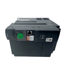
Need a Replacement Altivar Drive?
Browse new original Altivar drives for maintenance, troubleshooting, and replacement projects.
- New original parts
- Fast response
- Global shipping
3. Confirm Whether the PLC or Servo Hardware Actually Failed
A stopped machine is a symptom. It does not identify which component needs replacement.
The following table lists areas to investigate using the applicable manufacturer procedures. It is a starting point for qualified troubleshooting, not a diagnosis.
| Observed condition | Areas to investigate before ordering hardware |
|---|---|
| PLC indicators are dark | Incoming supply, control power, protective devices, connections, and the PLC power supply |
| PLC is running but the machine will not cycle | Machine permissives, input states, communications, sequence conditions, and connected equipment |
| Servo drive shows a disabled state | Enable conditions, safety-system status, and required supply conditions |
| Servo reports an overload or temperature fault | Mechanical load, binding, duty cycle, cooling, and the relevant motor or drive diagnostics |
| Servo reports a feedback fault | Feedback cable, connectors, configuration, and the motor feedback device |
| Several devices fail simultaneously | Shared power, network infrastructure, or another common upstream event |
For example, Schneider Electric’s guidance for a Lexium 32 “DIS” condition directs attention to safety-input status and mains-supply conditions. That example illustrates why a disabled drive should not automatically be treated as failed hardware. These checks are specific to that product family and do not justify bypassing a safety circuit. Schneider Electric: Diagnosing “DIS” on Lexium 32 Drives
Replacement becomes a reasonable next step when the applicable diagnostic process points to a defective component and the conditions that could damage its replacement have been addressed.
If the evidence remains unclear, provide the incident record to the machine builder or manufacturer’s technical support team. Repeatedly swapping components without narrowing the fault can extend downtime and put the spare at risk.
4. Verify the Replacement Before Authorizing Dispatch
During an emergency, maintenance and purchasing should use the same equipment specification. A photograph of the front panel or a partial model number is rarely sufficient.
PLC Replacement Checklist
Confirm the complete catalog number and suffix, then check:
- Hardware revision and supported firmware.
- Engineering software version and access to the editable project.
- Power-supply and rack or base compatibility.
- Local and remote I/O configuration.
- Communication interfaces and required network settings.
- Any application-specific memory, licensing, or expansion requirements.
- The recovery plan for retained values and machine settings.
Rockwell Automation’s Product Compatibility and Download Center supports checking product combinations, firmware, software, and related compatibility information. This is a useful reminder that physical fit alone does not establish a suitable PLC replacement. Rockwell Automation: Product Compatibility and Migration
Do not assume that installing the newest firmware will produce the quickest recovery. Use a version supported by the controller, engineering tools, and machine application.
A project from another machine also requires verification. Similar machines may have different I/O assignments, options, calibration values, or network identities.
Servo Drive and Motor Replacement Checklist
First identify what is being replaced: the drive, motor, feedback device, cable, or another part of the axis.
For a drive replacement, verify the full model reference, supply requirements, approved motor compatibility, feedback interface, communication option, and relevant safety configuration.
For a motor replacement, verify the approved drive pairing, electrical characteristics, encoder type, brake option, mounting dimensions, shaft arrangement, and connector configuration.
Schneider Electric’s Lexium 32S motor-replacement instructions explicitly warn that mechanically compatible connectors do not prove that a motor and drive combination is approved. The same instructions also require attention to encoder settings after replacement. Treat these as model-specific requirements to check in the applicable manual. Schneider Electric: Lexium 32S Motor Replacement
An alternative model should enter a documented compatibility review before purchase. Emergency availability does not eliminate engineering approval.
- PLC Solutions
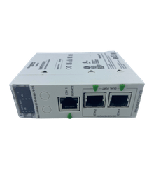
Find the Right PLC for Your System
Explore new original PLC CPUs, I/O modules, power supplies, and communication units for maintenance and automation projects.
- New original parts
- Fast response
- Global shipping
5. Prepare the Recovery Files and Installation Record
A compatible spare is only part of the recovery package.
Before installation, identify which information must be restored and who is responsible for restoring it.
| Replacement | Recovery information to prepare |
|---|---|
| PLC CPU | Approved project, compatible software, I/O configuration, network settings, and relevant retained data |
| Servo drive | Approved parameter backup, motor selection, communication settings, and machine-specific axis configuration |
| Servo motor | Approved pairing information, feedback configuration, and the required position-reference verification procedure |
| Communication or I/O module | Module configuration, addressing, and dependencies in the machine project |
Preserve wiring identification and connection records before removal, following the equipment instructions. Record the removed and installed equipment references and serial numbers.
Do not introduce several unrelated changes during the replacement. If hardware, firmware, wiring, and application logic all change together, identifying the cause of a remaining problem becomes harder.
Where a change is unavoidable, record it explicitly in the recovery plan.
6. Recommission in Stages Before Returning to Production
A replacement powering up without an alarm is an initial check. Production release requires evidence that the machine operates correctly with the replacement installed.
Use the machine builder’s commissioning procedure and assign responsibility for each stage.
| Stage | What the team needs to establish |
|---|---|
| Installation review | Correct equipment, connections, mounting, grounding, and other model-specific installation requirements |
| Controlled power-up | Expected equipment status, correct application or configuration, and stable communications |
| Functional checks | Relevant inputs, outputs, permissives, and machine functions behave as intended |
| Safety verification | Affected safety functions have been verified under the applicable validation procedure |
| Axis verification | Direction, reference position, travel limits, and brake-related behavior meet the approved procedure where applicable |
| Process verification | The machine completes representative operations with acceptable process results |
| Production release | The responsible person records acceptance and any remaining restrictions |
Do not use forced outputs, defeated interlocks, or improvised motion commands to accelerate this process.
For servo work, follow the approved procedure for any movement test. The appropriate conditions depend on the machine, load, axis arrangement, and safeguarding. There is no universal jog sequence that safely applies to every installation.
If an alarm returns, stop and reassess the evidence. A replacement that develops the same fault may be revealing an unresolved system problem.
- HMI Replacement
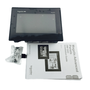
Upgrade or Replace Your HMI
Find compatible HMI panels for discontinued models, machine upgrades, and operator interface replacement.
- New original parts
- Fast response
- Global shipping
Frequently Asked Questions
Follow the manufacturer’s fault procedure. A reset may be appropriate after the underlying condition has been corrected, but clearing an alarm does not demonstrate that the cause is gone. Preserve available diagnostic evidence first when safe, and investigate recurring faults instead of repeatedly resetting them.
Do not assume it can. Establish how the correct machine application and configuration will be recovered before treating a new controller as a complete solution. If the project is unavailable, contact the machine builder or responsible controls engineer to identify an approved recovery route.
Only when the diagnosis or approved replacement plan supports doing so. A fault reported by the drive may originate in the motor, feedback system, cabling, mechanical load, or another part of the installation. Identify the affected component and verify the approved drive–motor combination.
Save the verified working project and parameters, update the installed-equipment record, and document the fault cause and corrective action. Review whether the spare stock, backups, or response procedure need improvement before the next incident.
Power your projects with brand-new, original Omron, Mitsubishi, Schneider PLC – in stock, ready now!
Coordinate Purchasing With the Recovery Plan
Send a replacement inquiry as soon as maintenance has identified the required component, while continuing the authorized recovery preparation.
A useful inquiry includes the complete model reference, quantity, relevant revision requirements, delivery destination, required arrival date, and whether an alternative can be considered.
Ask the supplier to confirm the actual item offered, its condition, availability, and dispatch timing. Separate dispatch expectations from the date the machine can return to service; installation and commissioning still require time.
For sourcing support, send these details to Kwoco and request confirmation of the proposed component and delivery options before placing the order.
Contact Us
Just fill out your name, email address, and a brief description of your inquiry in this form. We will contact you within 24 hours.
Product Category
Hot Sale Products
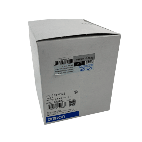
Omron CPU Unit CJ2M-CPU32
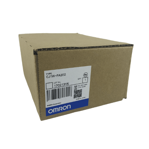
Omron PLC CJ1W-PA202 Supplier in China
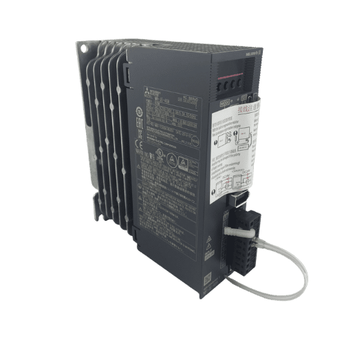
Mitsubishi MR-JE Series 400w Servo Drive MR-JE-40A
Need a Fast Match?
Share your model or spec and our team will help you find the right fit-fast.
- Expert support
- Quick response
- Competitive price
- +86-755-81481609
- [email protected]
You May Also Find These Topics Interesting
Choosing the Right Terminal Block: A Complete Guide
Terminal blocks are essential components in electrical systems, ensuring organized and secure connections between multiple wires. These devices come in a variety
Essential Guide to PLC Systems for Engineers
Essential Guide to PLC Systems for Engineers Do you want to streamline your industrial automation processes but are unsure where to start?

NC vs CNC: Understanding the Differences Between NC and CNC Machines
This article dives into the world of NC (Numerical Control) and CNC (Computer Numerical Control) machines, explaining their key differences and why