Guide to PLC Analog I/O for Automation Engineers
If you’re an automation engineer, this article will give you the foundational knowledge you need to work confidently with analog signals in a PLC environment. By the end of this read, you’ll have a better understanding of voltage and current, how to properly interface with analog inputs, and how to optimize your systems for better performance.
So, let’s explore how you can improve your workflow and efficiency by mastering PLC analog input and output systems.
Table of Contents
What is Analog Input in PLC Systems?
Analog input is the process of receiving continuous signals (usually voltage or current) from external devices like sensors, which can represent real-world variables such as temperature, pressure, or level. In a PLC system, these inputs are essential for monitoring and controlling industrial processes.
The PLC analog input module is responsible for converting the incoming analog signals into digital data that the PLC can process.
Types of Analog Signals
Analog inputs can be in the form of either voltage or current. Common voltage levels include 0-5V, 0-10V, or 4-20mA, while current signals typically range from 4-20mA. These signals vary continuously, unlike digital signals that are either on or off. Proper conversion of these signals is crucial for accurate system performance.
Key Components
The input card in the PLC is typically designed to handle a specific type of analog input (voltage or current). The analog input module plays a critical role by converting the signal into a form that the PLC system can interpret. This conversion allows the automation system to make data-driven decisions based on real-world inputs.
2.How Do Voltage and Current Affect PLC Analog Inputs?
Understanding how voltage and current interact with your PLC system is fundamental. Both voltage and current signals are used to communicate with various sensors, providing input data that can control operations like speed, temperature, and pressure.
But why are voltage and current critical, and how do they influence the operation of your PLC analog input system?
The Impact of Voltage
Voltage signals are typically used in situations where the measurement of a physical quantity is required. For example, temperature sensors (such as RTDs and thermocouples) often output voltage signals.
These sensors send data as a range of voltages (e.g., 0-5V, 0-10V), which must be accurately interpreted by the PLC input to ensure the correct process control.
The Role of Current
On the other hand, current signals (typically 4-20mA) are more robust in noisy industrial environments. Current tends to be less susceptible to voltage drops over long distances, making it ideal for applications where precise data transmission is critical.
For example, when working with pressure sensors or flow meters, current signals provide reliable data for the PLC system to process.
What is the Role of Sensors in Analog Input and Output Systems?
Sensors are the backbone of analog input and output systems. They gather real-world data and convert it into a signal that the PLC can understand. Sensors such as temperature sensors, load cells, and pressure switches are integral to capturing environmental data that automation systems need to function.
Types of Sensors Used in PLC Systems
Common types of analog sensors include RTDs, thermocouples, and load cells, each of which provides a unique type of signal to the PLC. For example, RTDs output a resistance value that can be converted to a voltage signal for PLC analog input, while load cells provide strain gauge measurements converted to an analog signal.
Challenges with Sensors
When working with analog sensors, one must ensure that the sensor is properly calibrated to provide accurate readings. Wiring and shielding are also important to reduce noise and interference, which can affect the integrity of the analog signals being sent to the PLC system.
How to Troubleshoot Analog Input Issues in PLC Systems?
In an automation environment, analog input problems can be caused by a variety of factors such as poor wiring, signal degradation, or issues with the PLC analog input module. Troubleshooting these problems effectively is key to ensuring optimal performance of the system.
Common Troubleshooting Steps
- Check Wiring Connections: Loose or incorrect wiring can lead to signal lossor incorrect readings. Ensure that all connections are secure and properly shielded.
- Verify Signal Scaling: If the signal outputfrom the sensor does not match the expected range, you may need to scale the input in the PLC configuration settings.
- Monitor Signal Integrity: Use a voltmeteror oscilloscope to verify that the analog input matches the expected values. Issues with voltage drops or current leakage could cause erroneous readings.
Advanced Troubleshooting Tools
For more complex issues, automation engineers may use advanced diagnostic tools such as signal converters or analog-to-digital converters (ADC) to identify problems in the PLC analog input system. These tools can help pinpoint issues related to voltage or current signal calibration.
What Are the Best Practices for Scaling Analog Inputs in Automation?
When dealing with large-scale automation systems, scaling analog inputs effectively is crucial. Whether you’re managing multiple sensors or working with high-precision equipment, proper scaling ensures that your PLC can handle a large number of inputs without sacrificing performance.
Tips for Scaling Analog Inputs
- Use Multiple Input Modules: When handling large numbers of analog inputs, it’s often best to use multiple PLC input modules. This allows for better distribution of load and ensures that each analog input moduleis not overloaded.
- Use Signal Conditioning: Signal conditioningtechniques, such as voltage dividers and amplifiers, help in scaling and adjusting signals for accurate processing. This is especially useful when dealing with low voltage signals.
- Consider Input Resistance: Different types of analog input moduleshave varying input resistance. Ensuring that your PLC system is compatible with your sensor’s resistance is essential to ensure accurate readings.
Frequently Asked Questions
What is the difference between voltage and current in analog inputs?
Voltage signals are continuous measurements typically used for sensors like thermocouples, whereas current signals are less affected by distance and are ideal for sensors like pressure switches or flow meters.
How do I calibrate a PLC analog input module?
Calibration usually involves adjusting the input scaling in the PLC configuration to match the expected range of the connected sensor or transmitter.
Why is my analog signal fluctuating?
Fluctuations can be caused by several factors, including loose connections, interference, or inadequate shielding of the wiring. Always ensure proper grounding and shielding in your wiring.
How do I scale a 4-20mA current input signal?
Scaling a 4-20mA current input involves converting the current values into a corresponding process variable range, often using a signal conditioner or by adjusting the scaling in the PLC system.
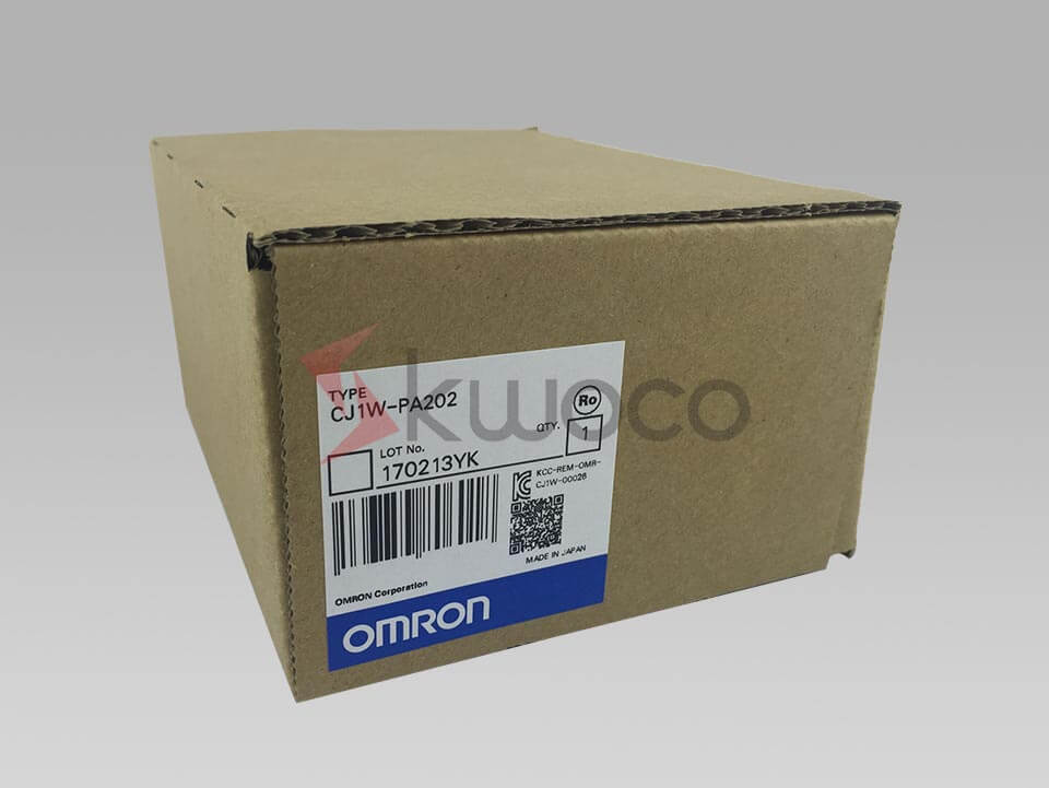
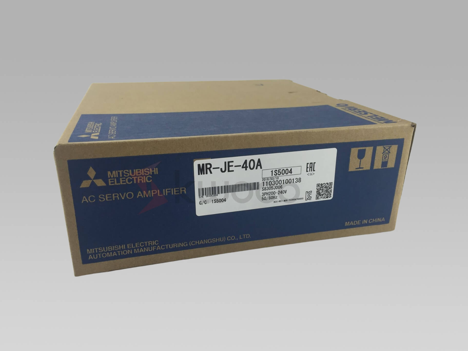
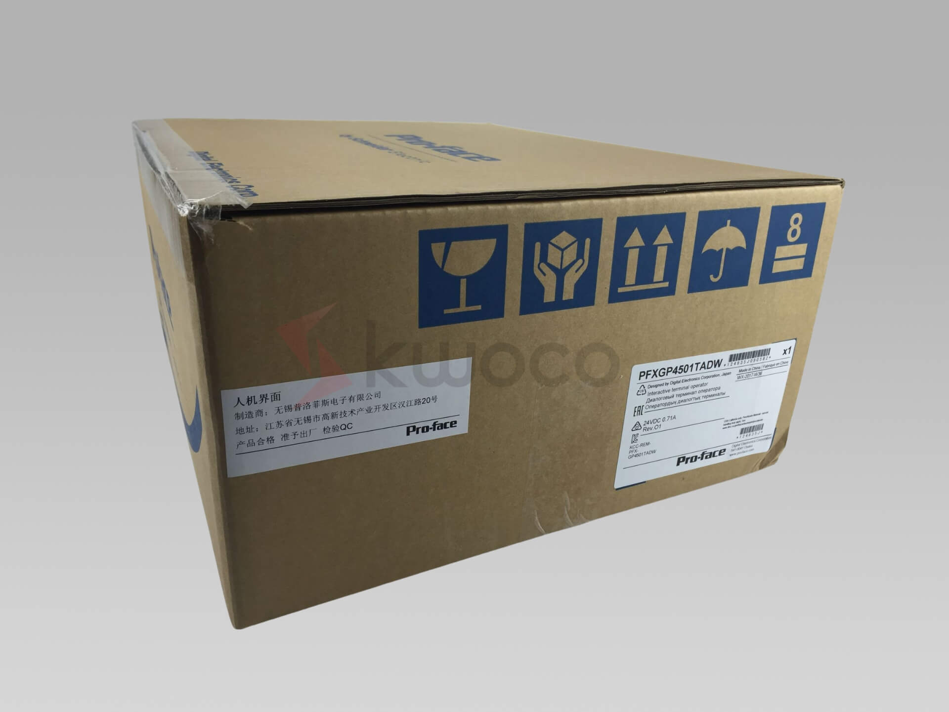
Power your projects with brand-new, original Omron, Mitsubishi, Schneider PLC – in stock, ready now!
Conclusion
- Analog inputand output signals are crucial in automating industrial processes and come in two main forms: voltage and current.
- Proper calibrationand signal conditioning are key to accurate data transfer between sensors and the PLC system.
- Troubleshooting analog input issues involves checking for wiring errors, verifying signal integrity, and ensuring correct scaling.
- Scaling analog inputsefficiently in large systems is essential to handle multiple sensors and prevent overload.
By understanding the fundamental concepts of PLC analog inputs and outputs, you can improve the reliability and accuracy of your automation systems, enhancing operational efficiency across your projects.
Looking for new, original PLCs for your projects? At Kwoco, we stock the latest PLCs from top brands like Omron, Mitsubishi, and Schneider. Shop with confidence—fast shipping, guaranteed quality! Buy Now
Contact Us
Just fill out your name, email address, and a brief description of your inquiry in this form. We will contact you within 24 hours.
You May Also Find These Topics Interesting

PLC Instruction Failures: A Troubleshooting Guide
In the domain name of modern industrial automation, the Programmable Logic Controller (PLC) plays an important role. It serves as the “brain” of the automation system, managing every stage of the manufacturing procedure by implementing a collection of exact guidelines.

Understanding the Key Components of a CNC Machine
Computer Numerical Control (CNC) machines have revolutionized modern manufacturing, offering unparalleled precision and efficiency. Understanding the components of a CNC machine is essential for anyone interested in machining, whether you’re a seasoned professional or a curious enthusiast. This guide explores the key components that make up a CNC machine, how they work together, and why they’re crucial for producing high-quality parts.

CNC Machine Mastery: Understanding the Crucial Difference Between Feed Rate and Spindle Speed
This article dives deep into the intricacies of CNC machining, specifically focusing on two critical parameters: feed rate and spindle speed. While seemingly simple, understanding the difference between feed rate and spindle speed is fundamental for anyone involved in CNC operation, from novice machinists to seasoned professionals. These factors are essential to achieving optimal efficiency, precision, and tool life in various CNC machining processes. With my experience in CNC Machines and Manufacturing plants, I aim to share insights that demystify these concepts.

