
NPN vs PNP Sensors: Key Differences Explained
Table of Contents
What Are NPN and PNP Sensors in Automation?
In the field of industrial automation, sensors play a vital role in detecting changes in physical conditions and sending signals to control systems like PLCs (Programmable Logic Controllers). Among these, NPN and PNP sensors are commonly used, but what exactly do these terms mean?
NPN and PNP refer to the transistor output configuration used by the sensor. This determines how conventional current flows through the load or PLC input when the sensor is activated:
- NPN Output (Sinking): When activated, the output transistor provides a path from the output terminal to 0 V. Conventional current flows from the positive supply, through the load or PLC input, into the sensor output, and then to 0 V. Within the NPN transistor, conventional current flows from collector to emitter.
- PNP Output (Sourcing): When activated, the output transistor connects the output terminal to the positive supply. Conventional current flows from the positive supply, through the sensor output, through the load or PLC input, and then to 0 V. Within the PNP transistor, conventional current flows from emitter to collector.
Understanding the sensor output type is important because it determines the required PLC input wiring. Using the correct NPN or PNP sensor ensures compatibility and helps prevent wiring faults or equipment damage.
How Do NPN and PNP Transistors Function?
To grasp how NPN and PNP sensors operate, it’s essential to understand the basic principles of transistors.
NPN Transistors
An NPN transistor consists of a layer of p-type semiconductor sandwiched between two layers of n-type semiconductor. When a positive voltage is applied to the base relative to the emitter, it allows a larger current to flow from the collector to the emitter. In the case of an NPN sensor:
- The output is connected to the collector.
- When activated, the sensor sinks current from the load to the ground.
PNP Transistors
Conversely, a PNP transistor has an n-type semiconductor layer sandwiched between two p-type layers (P-N-P configuration). To conduct, the base is biased negatively relative to the emitter. In a typical three-wire PNP sensor output:
- The emitter is connected to the positive supply, while the collector serves as the switched output terminal.
- When activated, the sensor sources current from the positive supply through the output to the load or PLC input.
- The load or PLC input is connected between the sensor output and 0 V to complete the circuit.
NPN vs PNP: What's the Key Difference?
Understanding the differences between the two sensor types is crucial for proper application.
Current Flow and Output Configuration
- NPN Sensors:
- Current flows from the load into the sensor and then to the ground.
- The sensor’s output is active low—it provides a path to the negative side when activated.
- Often referred to as sinking sensors.
- PNP Sensors:
- Current flows from the sensor into the load and then to the ground.
- The sensor’s output is active high—it connects the load to the positive side when activated.
- Known as sourcing output devices.
Wiring and Polarity
The sensor wiring differs between NPN and PNP sensors:
- NPN Sensor Wiring:
- Three-wire sensors: Brown (positive voltage), Blue (ground), Black (output).
- The load is connected between the positive voltage and the sensor’s output.
- PNP Sensor Wiring:
- Similar wire colors.
- The load is connected between the sensor’s output and the ground.
Table: NPN vs PNP Sensors
| Feature | NPN Sensor (Sinking) | PNP Sensor (Sourcing) |
|---|---|---|
| Current Direction | Load → Sensor → Ground | Sensor → Load → Ground |
| Output State When Active | Provides path to negative power (ground) | Provides path to positive voltage |
| Common Use | Used with plc input modules that expect sinking inputs | Used with PLCs expecting sourcing inputs |
Understanding these fundamentals helps in choosing the correct sensor for your industrial control applications.
How to Wire NPN and PNP Sensors to a PLC Input?
Proper sensor wiring is essential for the flow of current and the overall functionality of your control system. Let’s explore how to wire both types of sensors.
Wiring an NPN Sensor
- Connect the Brown Wire: Attach to the positive voltage supply (e.g., +24 VDC).
- Connect the Blue Wire: Attach to the ground (negative power).
- Connect the Black Wire (Output): Connect to the plc input module’s input terminal.
- Load Connection: The load or PLC input module is connected between the positive voltage and the sensor’s output.
Wiring a PNP Sensor
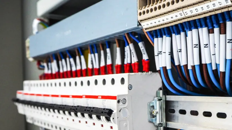
- Connect the Brown Wire: Attach to the positive voltage supply.
- Connect the Blue Wire: Attach to the ground.
- Connect the Black Wire (Output): Connect to the PLC input module.
- Load Connection: The load or PLC input is connected between the sensor’s output and the ground.
Tips for Correct Wiring
- Check the PLC Input Module: Ensure it supports the sensor type (sinking or sourcing).
- Use Proper Cables: Use cables that match the sensor’s specifications, like those offered by Omron Sensors.
- Safety First: Always disconnect power before wiring to prevent electrical hazards.
Which Sensor Type Is Right for Your Control System?
Choosing between NPN or PNP sensors depends on several factors related to your specific application.
Compatibility with PLCs
- Check PLC Specifications: Some PLCs, like Mitsubishi PLC, may favor one sensor type.
- Input Module Type: Determine if your input module is designed for sinking or sourcing inputs.
Industry Standards
- Regional Preferences: European industries often use PNP sensors, while Asian markets may prefer NPN sensors.
- Equipment Compatibility: Ensure sensors match other components, such as relays or solid-state outputs.
Application Requirements
- Environmental Conditions: Consider factors like electrical noise, which may affect sensor performance.
- Safety Considerations: PNP outputs are generally safer in environments where accidental grounding could occur.
Consultation and Support
- Manufacturer Guidance: Consult manufacturers like Omron PLC for recommendations.
- Expert Advice: Collaborate with technicians and engineers experienced in industrial automation.
Making an informed decision ensures optimal performance and longevity of your control system.
Frequently Asked Questions
NPN and PNP refer to the arrangement of semiconductor materials in the transistors:
- NPN: Negative-Positive-Negative
- PNP: Positive-Negative-Positive
These configurations influence how the transistor used in the output functions.
It’s not recommended. NPN and PNP sensors have different wiring requirements and output configurations. Using the wrong type can cause issues with the plc input module and overall system functionality.
PNP sensors supply positive voltage to the load, which can be safer in situations where accidental grounding might occur. This reduces the risk of unintended activation compared to NPN sensors.
Check your PLC’s input specifications:
- Sinking Inputs: Require PNP sensors.
- Sourcing Inputs: Require NPN sensors.
Refer to the PLC’s manual, or consult with the manufacturer or a professional.
- Sourcing (PNP): The sensor provides (sources) current to the load.
- Sinking (NPN): The sensor receives (sinks) current from the load.
Power your projects with brand-new, original Omron, Keyence, Panasonic sensors – in stock, ready now!
Conclusion
Understanding the nuances of NPN vs PNP sensors is essential for the reliability and efficiency of your control systems. By knowing the differences between NPN and PNP, how they interact with plc input modules, and the implications for your wiring configurations, you can make informed decisions that enhance system performance.
Remember:
- Always consult the manufacturer’s documentation.
- Consider the specifics of your application.
- Seek advice from experienced professionals when needed.
For further reading and resources, check out our articles on PLCs, Omron Sensors, and Relays.
Contact Us
Just fill out your name, email address, and a brief description of your inquiry in this form. We will contact you within 24 hours.


You May Also Find These Topics Interesting

Navigating the Future: Unpacking the Current State of the Industrial Automation Industry
The industrial automation industry is evolving at an unprecedented pace. This article delves into the current state of this dynamic sector, exploring the key trends, market size, and future projections. It’s a must-read because it provides a comprehensive overview of where the industry stands today and where it’s heading, offering valuable insights for anyone interested in or involved with industrial automation.
RTD and Thermocouples: Vital Sensors for Industrial Automation
In the realm of industrial automation, accurate temperature measurement is crucial for maintaining optimal operations and ensuring product quality. This article delves into the intricacies of Resistance Temperature Detectors (RTDs) and thermocouples, two of the most widely used temperature sensors.
7 Common Servo Motor Failures
7 Common Servo Motor Failures As a seasoned engineer with extensive experience in industrial automation, I’ve seen my fair share