Mastering PLC Panels: A Guide to Reading Wiring Diagrams
- kwoco-plc.com
- October 9, 2024
- 10:25 pm
Together, we’ll demystify PLC panels and wiring diagrams, making them less of a roadblock and more of a stepping stone!
PLC panels and wiring diagrams aren’t as complicated as they seem. Once you grasp a few key points, you’ll be able to read them with ease.
Table of Contents
What is a PLC Panel, and What Does It Do?
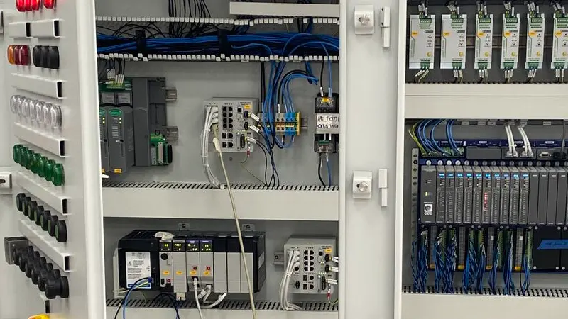
A PLC panel is the core brain controlling industrial equipment. It typically includes a PLC unit, I/O modules, HMI (Human-Machine Interface), power supply, and other auxiliary devices. Think of it like the central control system of a car, coordinating each part to work smoothly.
However, unlike a car, every connection in a PLC panel matters. A single wiring mistake could bring the entire system to a halt. That’s why learning to read wiring diagrams is so crucial.
What Are the Key Components in a PLC Panel, and How Do You Identify Them?
As an engineer, it’s crucial to understand each component in a PLC panel and recognize their symbols on wiring diagrams. Here are some common power and control components:
A) Power Components
- Rotary Disconnect Switch: Used for connecting the incoming power supply. It can be turned on or off using a handle on the panel door.
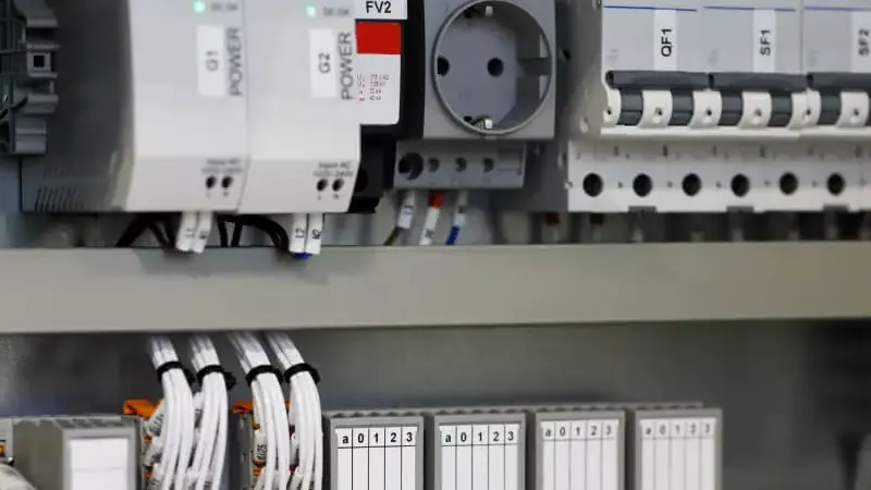
- Power Distribution Block: Splits larger wires into smaller ones, making connections with other electrical components easier.
- Relays and Contactors: Control mechanical operations based on commands from the PLC. Simple relays control lights, while contactors manage three-phase motors.
- Main Circuit Breaker: Controls the power switch for the entire circuit.
B) Control Components
- PLC: The heart of the panel, acting as the CPU, responsible for data processing and logic operations.
- HMI: Human-Machine Interface (HMI) offers a graphical interface for operators to monitor and control the PLC’s operations.
- I/O Modules: Connect the PLC to field devices; input modules receive signals from sensors, while output modules control devices like motors.
How Do You Read PLC Wiring Diagrams? What Are the Rules?
Mastering a few key rules is essential for reading PLC wiring diagrams:
- Read from Left to Right, Top to Bottom: Like reading a book, the reading sequence for wiring diagrams is typically from left to right, top to bottom.
- Use Symbols for Quick Location: The symbols on wiring diagrams represent each component’s position and connections. Familiarizing yourself with these symbols allows you to quickly pinpoint key points in the circuit.
- Pay Attention to Numbering Systems: Many wiring diagrams use page and column numbers, such as “35.2,” indicating that a component is on page 35, column 2.
How to Quickly Master PLC Panel Wiring Diagrams?
- Start with the Main Power, Then Move to Control Circuits: The main power section is usually in the upper left corner of the diagram. Verify the main power connections before checking other control circuits.
- Identify Inputs and Outputs: Inputs and outputs are often marked with different colors or symbols. Make sure every input device (like sensors) and output device (like motors) is connected correctly.
Why Are Wiring Diagrams So Important for Engineers?
Wiring diagrams are not just installation guides; they also help us troubleshoot quickly. Whenever an issue occurs, we can follow the wiring diagram step by step to locate the problem, avoiding extended downtime.
How to Quickly Locate Fault Points Using Wiring Diagrams?
The key to quickly finding fault points through wiring diagrams is logical troubleshooting and step-by-step inspection.
First, verify whether the power input is normal by checking the connections in the main power section of the diagram. If the system fails to start, it could be a power or fuse issue.
Next, inspect the input and output modules to ensure signals are transmitted correctly. Using the symbols on the wiring diagram, you can narrow down the problem to a specific sensor or actuator, making troubleshooting more efficient.
For example, if a sensor has no signal, check its wiring or replace the module.
Wiring diagrams also help us understand the control circuit’s logic. By checking the logical control section, you can verify whether the PLC’s input signals and output controls align with the design logic.
If a part of the control circuit is malfunctioning, the diagram allows you to identify the issue quickly, avoiding blind repairs. Using tools like a multimeter to measure current and voltage can further validate the circuit’s functionality.
How to Maintain the Electrical Wiring of a PLC Panel?
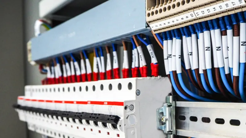
The primary step in maintaining PLC panel wiring is to regularly check the tightness of all connections. Due to vibration and temperature changes in industrial environments, screw terminals may become loose, leading to unstable signal transmission or short circuits.
Ensuring that all connections are secure is crucial. A thorough inspection every few months can significantly improve system reliability.
Additionally, keep the panel dust-free and moisture-resistant. PLC panels often house many delicate electronic components, and dust and moisture can cause terminal corrosion or short circuits.
Regularly clean the inside of the panel with compressed air while the system is running, and avoid placing the panel in highly humid environments. If installation in a damp area is unavoidable, use a waterproof casing or desiccants to extend the panel’s lifespan.
Finally, replace aging wires and components promptly. Long-term use can cause wires to age, leading to insulation damage and increasing the risk of electric leakage or short circuits.
Use the specifications in the wiring diagram to select replacement components that match the original model, ensuring safety and stability.
With these maintenance measures, you can not only extend the life of your PLC system but also reduce downtime caused by wiring issues, keeping your operations running smoothly.
Frequently Asked Questions
What Does “COM” Mean on a Wiring Diagram?
COM usually stands for “common,” serving as a shared connection point for multiple input or output devices. During wiring, it’s crucial to ensure the COM terminal is connected correctly.
How Can I Ensure Wiring Safety?
Use the right cables and terminal blocks, strictly follow the symbols and instructions on the wiring diagram, and most importantly, always perform wiring tasks with the power off.
Why Is It Important to Follow the Wiring Diagram Strictly?
Wiring diagrams are designed based on system requirements and functions. Any deviation could lead to equipment damage or even safety hazards.
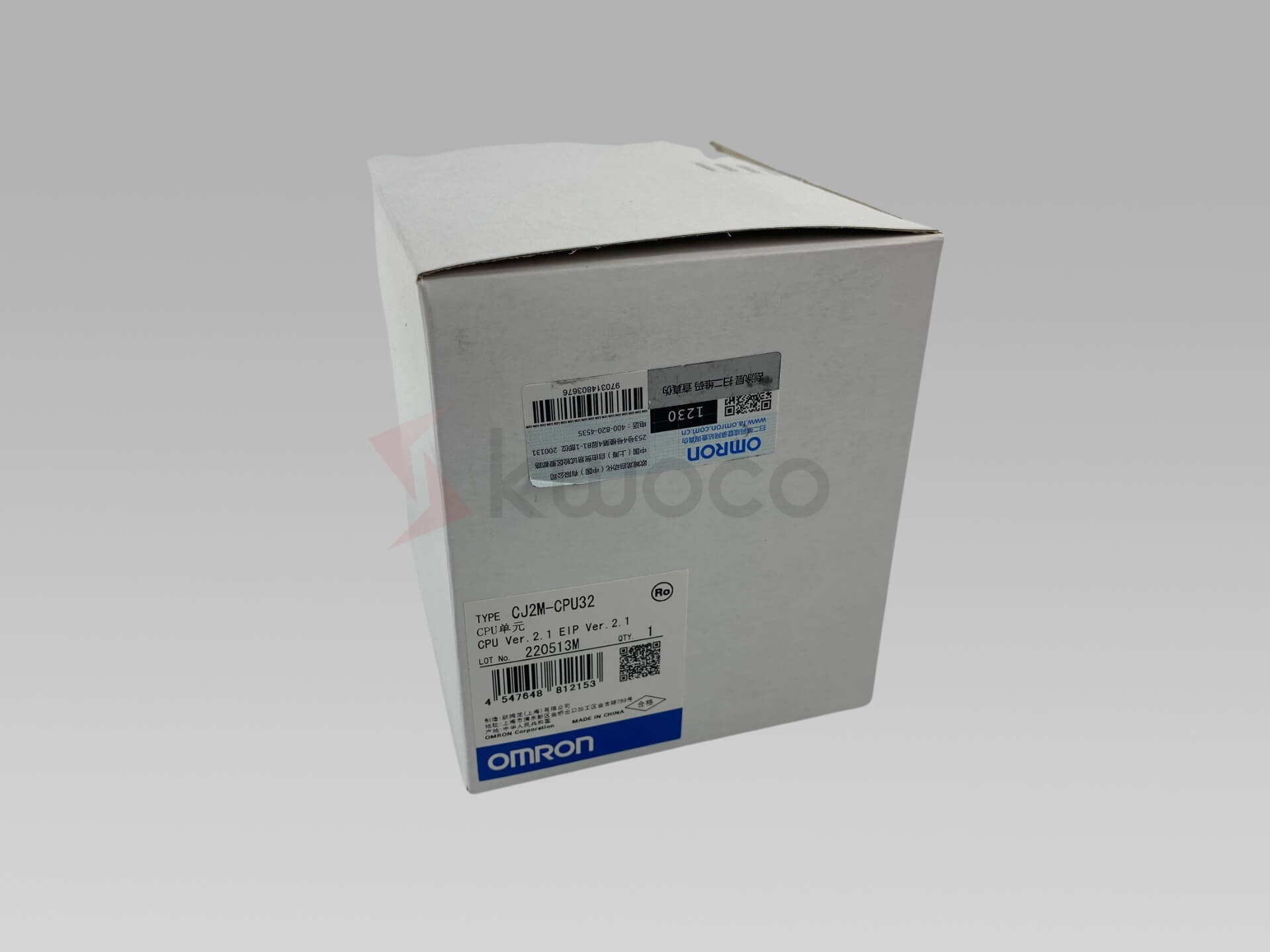
Power your projects with brand-new, original Omron, Mitsubishi, Schneider PLC – in stock, ready now!
Conclusion
Learning to read PLC panels and wiring diagrams is an essential skill that not only improves work efficiency but also enhances your professional expertise. I hope this article helps you master this skill and makes wiring a less daunting task!
Looking for new, original PLCs for your projects? At Kwoco, we stock the latest PLCs from top brands like Omron, Mitsubishi, and Schneider. Shop with confidence—fast shipping, guaranteed quality! Buy Now
Contact Us
Just fill out your name, email address, and a brief description of your inquiry in this form. We will contact you within 24 hours.
You May Also Find These Topics Interesting

Recommended Omron PLC Suppliers in the UK: How to Find a Reliable Partner
In the ongoing electronic makeover of UK production, Omron PLCs have actually long been the favored selection for many automation engineers and procurement managers. Whether in food packaging, automotive manufacturing, or power control systems, Omron PLCs are trusted for their security, high performance, and exceptional compatibility.
Introduction to Programmable Logic Controllers: Your Gateway to Industrial Automation
This article is a comprehensive guide to Programmable Logic Controllers (PLCs), exploring their fundamental role in modern industrial automation. From machinery and equipment factories to manufacturers and solution providers, PLCs are indispensable for streamlining operations and enhancing productivity. This article delves into the intricacies of PLCs, their programming, and their diverse applications.
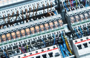
Understanding PLCs: Uses of Programmable Logic Controllers
Programmable Logic Controllers (PLCs) have become an integral part of modern industrial automation. If you’ve ever wondered how complex machinery and production lines perform tasks with such precision, the answer lies in the use of PLCs.

