Understanding Analog Inputs in PLC Systems: Bridging the Gap Between Digital and Analog Signals
Table of Contents
What is a PLC Panel, and What Does It Do?
- Temperature
- Pressure
- Flow rate
- Level
Why Use Analog Inputs?
- Precision: Analog inputs provide detailed information, allowing for precise control.
- Versatility: Can monitor a wide range of physical parameters.
- Real-Time Monitoring: Essential for processes that require continuous monitoring.
How Do Sensors Provide Analog Signals to PLCs?
Sensors are devices that detect changes in the environment and send information to other electronics, typically a PLC system. In the context of analog inputs, sensors play a pivotal role by providing analog signals that represent physical phenomena.
Common Analog Sensors
- Temperature Sensors: Such as thermocouples and Resistance Temperature Detectors (RTDs).
- Pressure Transducers: Convert pressure into an electrical signal.
- Flow Meters: Measure the flow rate of liquids or gases.
Process of Converting Physical Signals
- Sensing: The sensor detects a physical change.
- Signal Generation: The sensor produces an analog signal proportional to the change.
- Transmission: The signal is sent to the analog input module.
- Conversion: The PLC converts the analog signal into a digital value using an Analog-to-Digital Converter (ADC).
For example, a temperature sensor may produce a voltage signal that increases with temperature. This voltage is an analog input that the PLC can interpret and respond to accordingly.
Analog vs. Digital Inputs: Understanding the Differences
Understanding the differences between digital and analog inputs is crucial in automation.
Analog Inputs
- Represent continuous values.
- Can sense a wide range of voltage or current levels.
- Provide detailed information about a physical parameter.
- Use analog input modules.
Digital Inputs
- Represent discrete states: 0 and 1.
- Typically read as ON or OFF.
- Ideal for simple signals like a pressure switch or binary sensor.
- Use digital input modules.
Key Differences
- Information Detail: Analog provides more nuanced data; digital is binary.
- Signal Type: Analog signals include a range of voltages; digital signals are fixed levels.
- Processing: Analog signals require conversion to digital form for processing in a PLC.
How Do Analog Input Modules Work in PLC Systems?
An analog input module in a PLC system is designed to read analog signals from field devices and convert them into digital values that the PLC can process.
Components of an Analog Input Module
- Analog-to-Digital Converter (ADC): Converts the analog signal to a digital value.
- Signal Conditioning: Adjusts the signal to a suitable range for the ADC.
- Isolation Circuits: Protect the PLC from voltage spikes.
Processing Analog Signals
- Signal Conditioning: The analog signal, such as a voltage signal, is conditioned to match the input range of the ADC.
- Conversion: The ADC converts the analog signal into a digital value, typically ranging from 0 to 1023 in a 10-bit system.
- Scaling: The PLC program scales the digital value to a meaningful analog value, representing the actual physical parameter.
Example
A 5 volts signal from a sensor is read by the analog input module. If the module’s range is 0 to 5 volts, and it’s a 10-bit ADC, the PLC will read a value of 1023, which can be scaled to represent full scale in the application.
Integrating Analog Inputs with Microcontrollers and PLCs
Both microcontrollers, like Arduino, and PLCs utilize analog inputs to interact with the physical world.
Using Analog Inputs with Microcontrollers
- Arduino has analog input pins that read voltage levels.
- The input voltage is typically between 0 and 5 volts.
- The microcontroller converts this voltage to a digital value for processing.
PLC Analog Inputs
- Designed for industrial applications.
- Can handle a wider range of input voltage and current signals.
- Provide signal conditioning and isolation.
Steps to Integrate Analog Inputs
- Connect the Sensor: Wire the sensor’s output to the analog input module.
- Configure the Module: Set the input type (voltage or current) in the PLC software.
- Program the PLC: Scale the input signals to usable units (e.g., temperature, pressure).
- Implement Control Logic: Use the analog data to make decisions in the PLC program.
Importance of Proper Integration
- Accuracy: Ensures that the analog signal is correctly interpreted.
- Safety: Protects equipment from incorrect voltage levels.
- Efficiency: Enhances the performance of the automation system.
Practical Applications of Analog Inputs
Analog inputs are used in various industries for:
- Process Control: Regulating variables like temperature and pressure.
- Data Acquisition: Collecting data for analysis and optimization.
- Automation: Controlling control valves, motors, and other actuators based on sensor in
Examples
- Temperature Control: Using a temperature sensor to regulate a heating system.
- Fluid Level Monitoring: Measuring the level in a tank using a pressure transducer.
- Speed Control: Adjusting the speed of a motor based on analog input from a potentiometer.
Frequently Asked Questions
Analog signals in PLCs are typically voltage or current signals. Common voltage ranges include 0 to 5 volts, 0 to 10 volts, and current ranges like 4-20mA.
An analog input module uses an Analog-to-Digital Converter (ADC) to convert the continuous analog signal into a digital value. This involves sampling the signal and quantizing it into binary numbers that the PLC can process.
Signal conditioning adjusts the analog signal to a level suitable for the ADC, filters out noise, and provides isolation. It ensures accurate and reliable readings from the analog input.
Yes, a potentiometer acts as a variable resistor and can provide a varying voltage signal proportional to its position. This analog voltage can be read by the PLC’s analog input module.
Resistors are used in voltage dividers and for current limiting in analog input circuits. They help in signal conditioning and ensuring that the input signal is within the acceptable range of the analog input module.
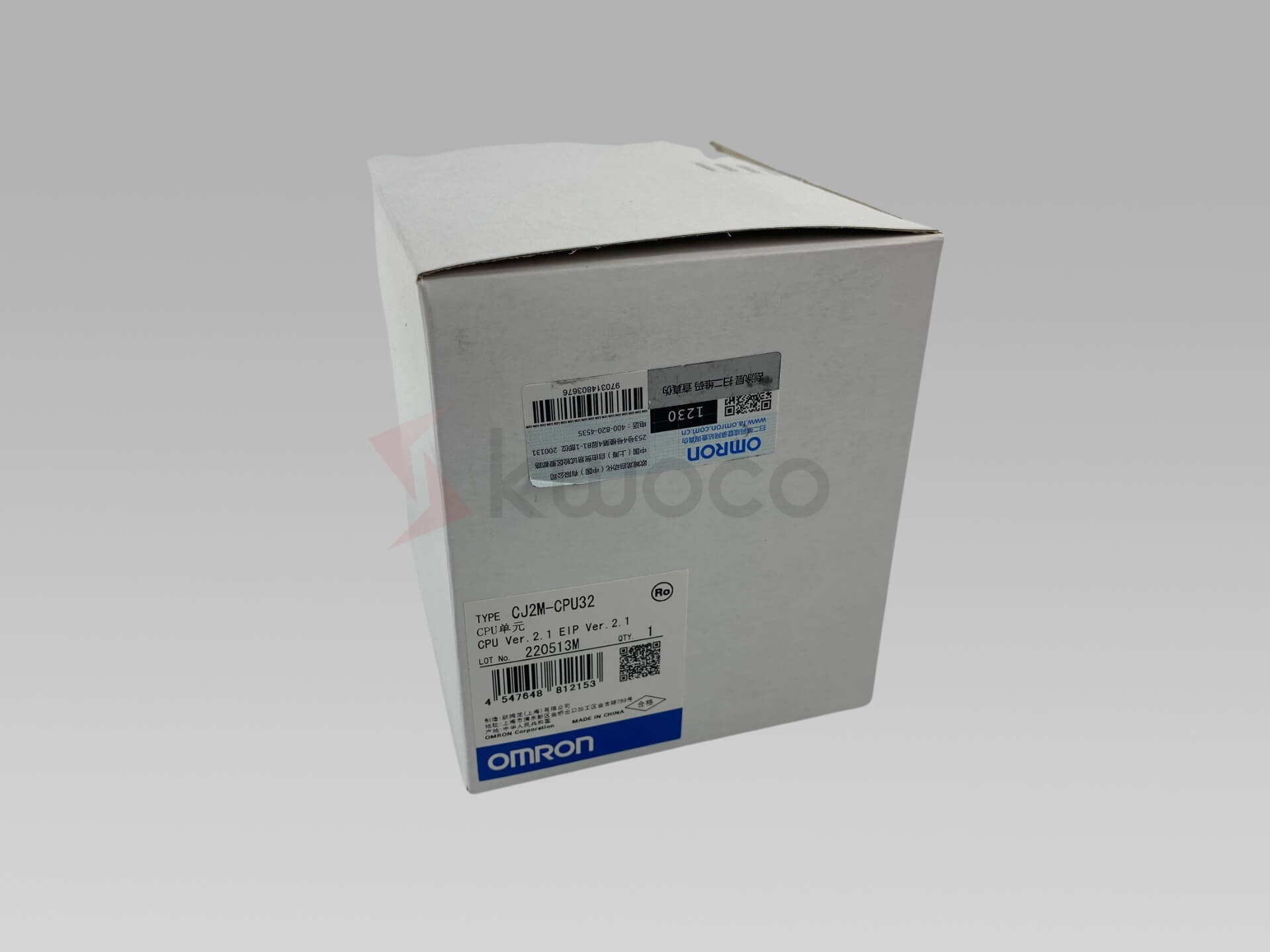
Power your projects with brand-new, original Omron, Mitsubishi, Schneider PLC – in stock, ready now!
Conclusion
– Analog inputs provide detailed information by representing physical quantities as continuous signals.
– Understanding the differences between digital and analog inputs is essential for effective automation.
– Sensors produce analog signals like voltage or current, which are read by the PLC’s analog input module.
– Signal conditioning and analog-to-digital conversion are vital processes in interpreting analog signals.
– Proper integration of analog inputs enhances the efficiency and reliability of PLC systems.
Looking for new, original PLCs for your projects? At Kwoco, we stock the latest PLCs from top brands like Omron, Mitsubishi, and Schneider. Shop with confidence—fast shipping, guaranteed quality! Buy Now
Contact Us
Just fill out your name, email address, and a brief description of your inquiry in this form. We will contact you within 24 hours.
You May Also Find These Topics Interesting

What is the Difference Between PLC, SCADA, and DCS?
In the field of industrial automation, selecting the right control system is crucial. However, the differences between PLC, SCADA, and DCS often cause confusion. As an engineer who has worked at Kwoco for many years, I understand the importance of these terms.

PLC Analog Input & Output: Testing & Troubleshooting Guide
Programmable Logic Controllers (PLCs) are the backbone of many industrial automation systems. They enable precise control over machines and processes, relying heavily on inputs and outputs (I/O) to communicate with external devices.

24VDC vs 120VAC: Understanding the Differences in Automation
When selecting control voltages for industrial automation, two common choices are 24VDC and 120VAC. But how do you decide which one is right for your application? In this article, we will break down the key differences between 24VDC and 120VAC, explore their uses in automation systems, and help you make an informed decision based on your needs.

