What is PLC Ladder Logic and How Does it Work?
Table of Contents
What Is Ladder Logic in PLC Programming?
Ladder logic is a graphical programming language used to develop software for PLCs. But what exactly makes ladder logic so indispensable in the world of automation?
The Origin and Purpose of Ladder Logic
Originally modeled after electrical relay circuits, ladder logic was designed to simplify the transition from relay logic hardware to programmable systems. It mimics the layout of electrical circuits, making it intuitive for engineers familiar with traditional circuit diagrams.
Structure of Ladder Logic Diagrams
A ladder logic diagram resembles a ladder, with two vertical rails and horizontal rungs. The left rail represents the power supply, while the right rail is the ground. Each rung represents a ladder logic instruction, defining a specific operation.
Why Ladder Logic Is a Preferred Programming Language
- Intuitive Design: Its graphical nature makes it easier to visualize and understand the control flow.
- Ease of Learning: Engineers can learn ladder logic quickly due to its resemblance to electrical schematics.
- Wide Acceptance: Being one of the oldest PLC programming languages, it’s widely supported across different PLC brands.
How Does Ladder Logic Work in a PLC?
Understanding how ladder logic works is crucial for effective PLC programming. Let’s explore the mechanics behind it.
The Flow of Logic from Left to Right
In ladder logic, the control flow moves from the left rail to the right, scanning each ladder logic rung sequentially. This mimics the flow of electricity in a physical circuit.
Input and Output Processing
- Inputs: These are conditions or signals read from sensors or user inputs. They are represented by symbols like contacts.
- Outputs: Actions executed by the PLC, such as activating motors or lights, represented by coils or other output symbols.
Logic Operations and Instructions
Ladder logic uses standard logic operations like AND, OR, and NOT to control the flow of the program. By combining these operations, complex control schemes can be implemented.
Key Symbols and Instructions in Ladder Logic
To effectively read ladder logic diagrams, familiarity with its symbols is essential.
Common Ladder Logic Symbols
| Symbol | Meaning |
|---|---|
| –[ ]– | Normally Open Contact (Input) |
| –[\]– | Normally Closed Contact (Input) |
| –( )– | Coil (Output) |
| –(M) | Memory Coil |
| –(T) | Timer |
| –(C) | Counter |
Understanding Ladder Logic Instructions
- Contacts: Represent input conditions.
- Coils: Represent output actions.
- Timers and Counters: Used for operations that require time-based control.
The Advantages of Using Ladder Logic for PLCs
Why do many engineers and technicians prefer ladder logic over other PLC programming languages?
Ease of Troubleshooting and Maintenance
The visual nature of ladder logic diagrams allows for easier troubleshooting. Technicians can quickly identify faulty rungs or logic errors.
Compatibility Across Different PLC Brands
Most PLC manufacturers support ladder logic, making it a universal language in industrial automation.
Flexibility and Scalability
From simple to complex systems, ladder logic programs can be scaled accordingly, providing flexibility for various applications.
How to Learn and Implement Ladder Logic Programming
Embarking on a journey to learn ladder logic? Here are some steps and tips to get you started.
Start with the Basics of Ladder Logic
- Understand the Symbols: Familiarize yourself with basic symbols and their functions.
- Study Simple Programs: Begin by analyzing simple ladder logic diagrams.
Practice with Real PLCs or Simulators
- Use Simulation Software: Tools like PLCSim allow you to write and test ladder logic programs without physical hardware.
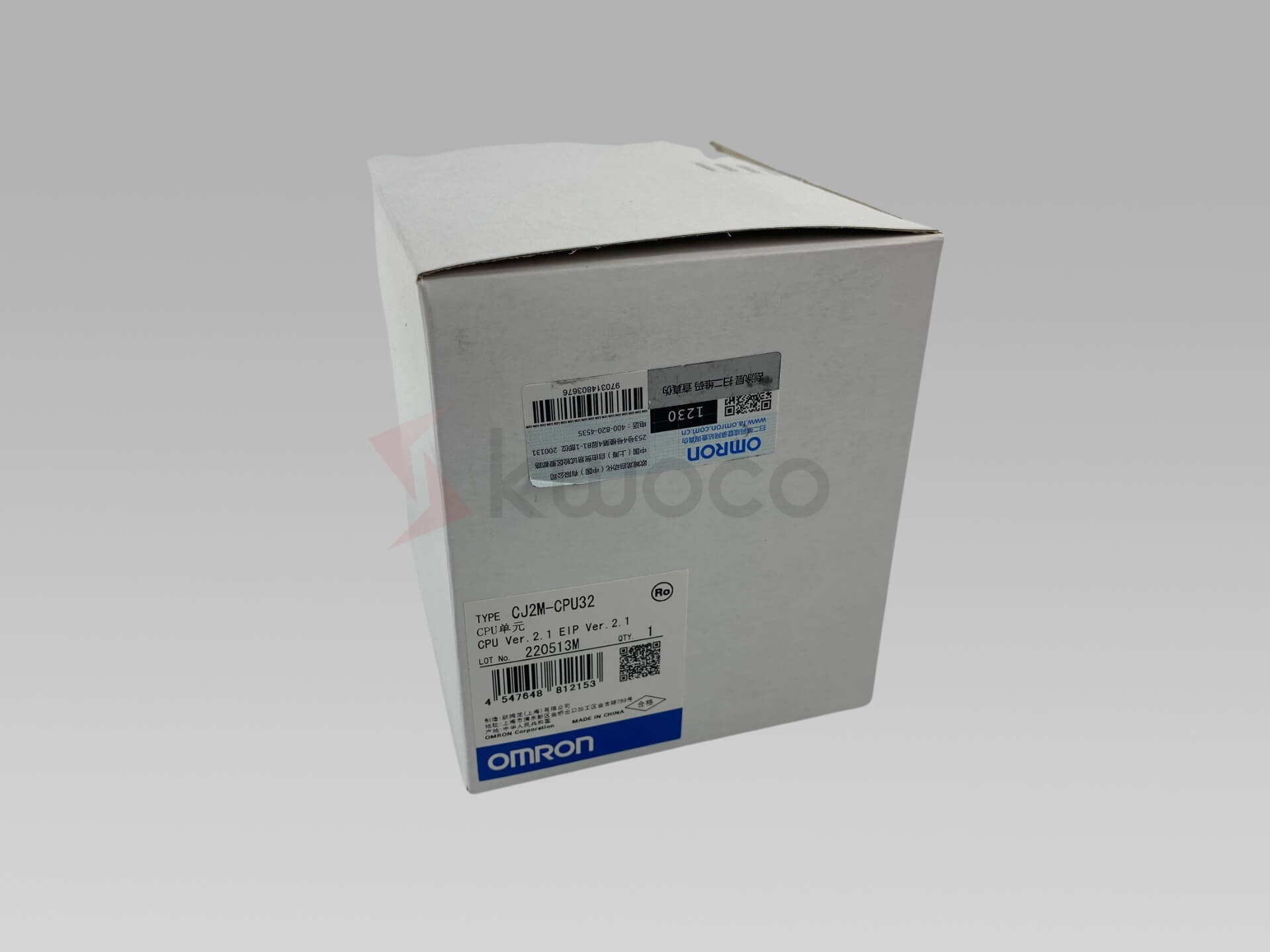
- Hands-On Experience: Working with actual PLCs like Omron PLC or Mitsubishi PLC enhances understanding.
Resources and Training
- Online Courses: Many platforms offer courses on PLC programming ladder logic.
- Workshops and Seminars: Attend industry events to gain insights and practical knowledge.
Frequently Asked Questions
Ladder logic is used as a programming language to create programs that instruct a PLC on how to perform control tasks.
While it may seem complex at first, ladder logic is relatively easy to learn, especially for those familiar with electrical control systems.
Most PLCs, including those from Schneider, support ladder logic, making it a widely used language in automation.
The basic components include contacts (inputs), coils (outputs), timers, counters, and rungs that represent the control logic.
Unlike text-based programming languages, ladder logic is graphical, making it more intuitive for designing and visualizing control processes.
Power your projects with brand-new, original Omron, Mitsubishi, Schneider PLC – in stock, ready now!
Conclusion
Ladder logic remains a fundamental skill in the field of industrial automation. Its intuitive design and widespread acceptance make it an ideal choice for programming PLCs. By understanding the basics of ladder logic, engineers and technicians can design, troubleshoot, and maintain complex control systems efficiently.
Looking for new, original PLCs for your projects? At Kwoco, we stock the latest PLCs from top brands like Omron, Mitsubishi, and Schneider. Shop with confidence—fast shipping, guaranteed quality! Buy Now
Contact Us
Just fill out your name, email address, and a brief description of your inquiry in this form. We will contact you within 24 hours.
You May Also Find These Topics Interesting

Comprehensive Guide to DC Motor and Controller
This comprehensive guide delves into the intricacies of DC drives, essential components in various industrial automation and motion control systems. Understanding DC drives is crucial for anyone involved in designing, operating, or maintaining systems that require precise control of motor speed and torque. Whether you are looking to enhance your knowledge or choose the right DC drive for your application, this guide provides the insights you need.

PLC Analog Input & Output: Testing & Troubleshooting Guide
Programmable Logic Controllers (PLCs) are the backbone of many industrial automation systems. They enable precise control over machines and processes, relying heavily on inputs and outputs (I/O) to communicate with external devices.

Troubleshooting Common PLC Failures: A Guide to Programmable Logic Controllers
Programmable Logic Controllers (PLCs) are the backbone of modern automation, orchestrating the seamless operation of machinery and industrial processes. However, like any technology, they can encounter issues that disrupt operations.

