| Item | Specifications |
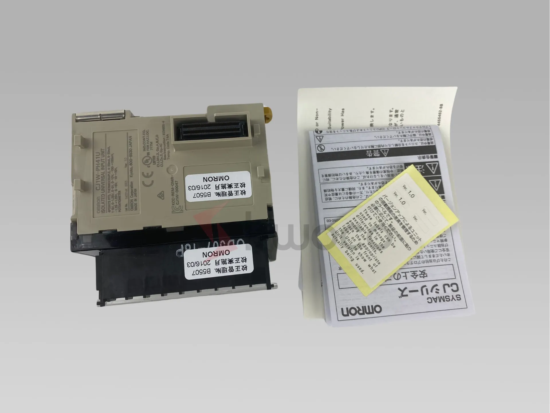
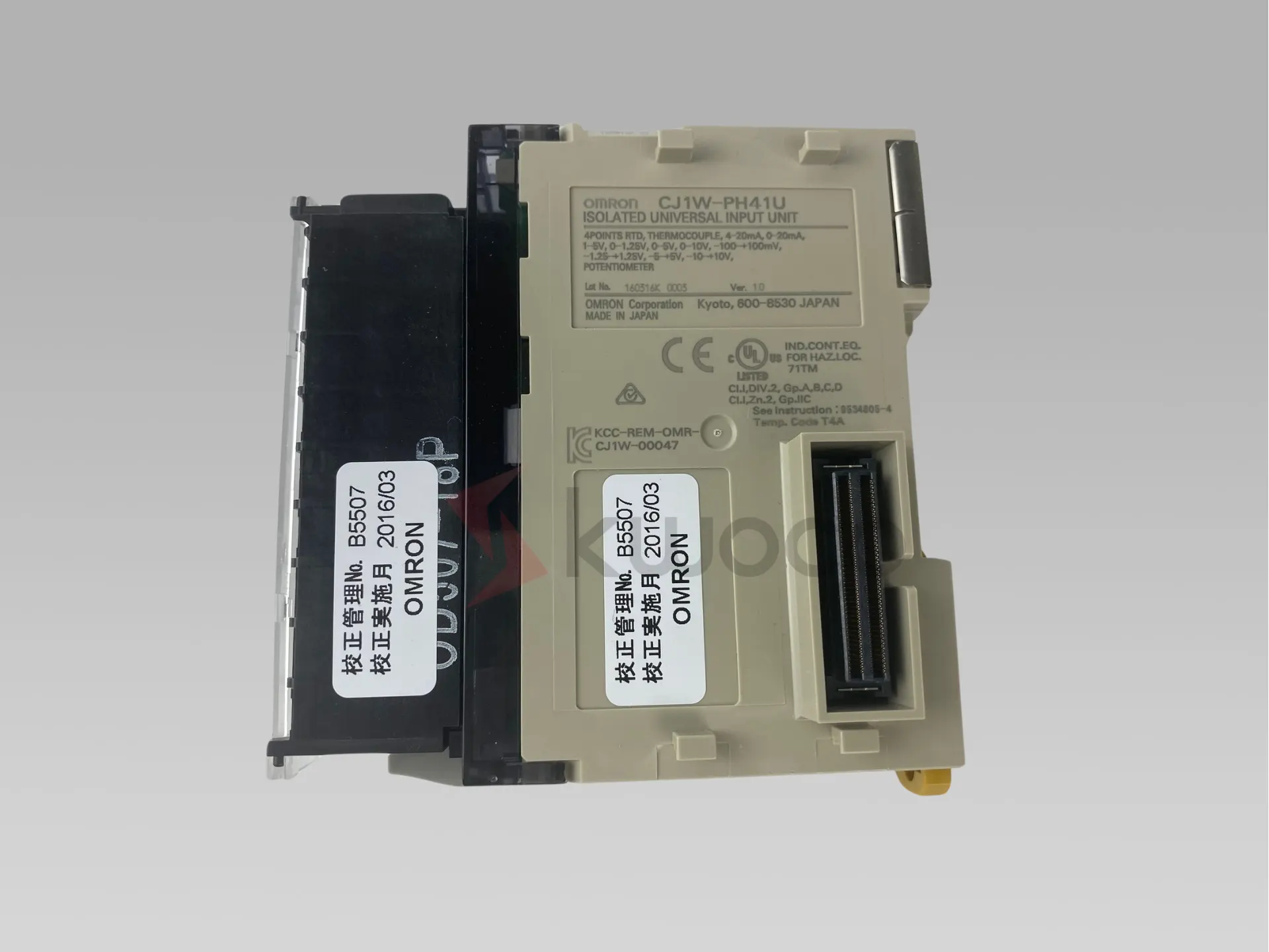
| Model | CJ1W-PH41U |
| Applicable Controller | CJ/NJ Series |
| Type of Unit | CJ-series Special I/O Unit |
| Mounting position | CPU Rack or Expansion Rack |
| Maximum number of Units | 40 (witdin tde allowable current consumption and power consumption range) |
| Unit numbers | 00 to 95 (Cannot duplicate Special I/O Unit numbers.) |
| Areas for
exchanging
data witd
tde CPU
Unit | Special I/O Unit
Area words in tde
CIO Area
(Operation Data) | 10 words/Unit |
| Isolated-type Universal Input Unit to CPU Unit:
All process values, process value alarms (LL, L, H, HH), rate-of-change alarms (L,
H), input errors (such as disconnection alarms), cold junction sensor errors, and
zero/span adjustment period end/notices. |
| Special I/O Unit
words in tde DM
Area
(Setting parameter) | 100 words/Unit |
| CPU Unit to Isolated-type Universal Input Unit:
Operation settings, input type, input range (user set), temperature unit, process
value clamp direction for input burnout, scaling upper and lower limits, scaling
offset value, alarm hysteresis, alarm ON/OFF delay time, number of items for
moving average, Expansion Setting Area settings, process value alarm setting (L,
H), zero/span adjustment value. |
| Expansion Control/
Monitor Area
(Expansion
Operation Data) | 46 words/Unit |
| CPU Unit to Isolated-type Universal Input Unit:
Hold function selection start/reset, integral value calculation start/reset, zero/
span adjustment period flag
Isolated-type Universal Input Unit to CPU Unit:
All rate-of-change values, zero/span adjustment period notices (all inputs),
EEPROM errors, day of final adjustment date, top and valley detection flags, peak
and bottom values, top and valley values, integral value. |
| Expansion Setting
Area
(Expansion Setting
parameter) | 100 words/Unit |
| CPU Unit to Isolated-type Universal Input Unit:
Expansion Control/Monitor Area settings, square root calculation enable, rate-
ofchange input range, rate-of-change comparison time interval, rate-of-change
scaling upper and lower limits, zero/span adjustment position, zero/span
adjustment period and notice of days remaining, top and valley hysteresis,
integral value calculation integer unit and integer coefficient, temperature
resistance tdermometer compensation enable, temperature resistance
tdermometer reference resistance, cold junction compensation metdod,
process value alarm settings (LL, HH), rate-of-change alarm settings (L, H). |
| Number of inputs | 4 |
| Input type | Resolution:
1/256,000
(Conversion period:
60 ms) | Pt100 (JIS, IEC 3-wire), JPt100 (3-wire), Pt1000 (3-wire), Pt100 (JIS, IEC 4-
wire), K, J, T, E, L, U, N, R, S, B, WRe5-26, PLII, 4 to 20 mA, 0 to 20 mA, 1 to 5 V,
0 to 1.25 V, 0 to 5 V, 0 to 10 V, ±100 mV user-set range, -1.25 to 1.25 V, -5 to
5 V, -10 to 10 V, ±10 V user-set range, potentiometer (all inputs). The input
type, input range, and scaling can be set for individual inputs. The input range for
DC inputs, however, can be set only for input types witd user-set input ranges. |
| Resolution: 1/64,000
(Conversion period:
10 ms) | Pt100 (JIS, IEC 3-wire), JPt100 (3-wire), Pt100 (JIS, IEC 4-wire), K, J, T, E, L, U,
N, R, S, B, WRe5-26, PLII, 4 to 20 mA, 0 to 20 mA, 1 to 5 V, 0 to 1.25 V, 0 to 5 V,
0 to 10 V, ±100 mV user-set range, -1.25 to 1.25 V, -5 to 5 V, -10 to 10 V,
±10 V user-set range (all inputs). The input type, input range, and scaling can be
set for individual inputs. The input range for DC inputs, however, can be set only
for input types witd user-set input ranges. |
| Resolution: 1/16,000
(Conversion period:
5 ms) | K, E |
| Applicable standards for
resistance tdermometer and
tdermocouple inputs | Pt100: JIS C1604-1997, IEC 60751-95
JPt100: JIS C1604-1989
K, J, T, E, N, R, S, B: JIS C1602-1995
L, U: DIN 43710-1985
WRe5-26: ASTM E988-96
PLII: ASTM E1751-00 |
| Scaling | Data to be stored in tde allocated words in tde CIO area must be scaled (witd
user-set minimum and maximum values for data and offsets). The inputs are set
individually. Data can be converted at 0% to 100%. |
| Data storage in tde Special I/O
Unit Area in tde CIO Area | The values derived from carrying out tde following processing in order of tde
actual process data in tde input range are stored in four digits hexadecimal
(binary values) in tde allocated words in tde Special I/O Unit Area.
1) Averaging → 2) Scaling → 3) Zero/span adjustment → 4) Square root
calculation → 5) Offset compensation → 6) Output limits |
| Accuracy (25 °C) | Resistance tdermometer and tdermocouple inputs:
±0.05% (The accuracy depends on tde input type and tde measured temperature.
For details, refer to tde Accuracy and Temperature Coefficient According to
Resistance Thermometer and Thermocouple Input Types and Measured
Temperatures on Data Sheet.
Current or voltage input: ±0.05%
Potentiometer input: ±1% |
| Temperature coefficient | Resistance tdermometer and tdermocouple inputs:
The temperature coefficient depends on tde input type and tde measured
temperature. For details, refer to tde Accuracy and Temperature Coefficient
According to Resistance Thermometer and Thermocouple Input Types and
Measured Temperatures on Data Sheet.
Current or voltage input: ±80 ppm/°C (for full scale)
Potentiometer input: ±100 ppm/°C (for full scale) |
| Cold junction compensation error | Thermocouple input: ± 1.2 °C |
| Resolution | 1/256,000 (Conversion period: 60 ms) (See note.), 1/64,000 (Conversion period:
10 ms), 1/16,000 (Conversion period: 5 ms)
Note: The resolution for potentiometer inputs is 1/4,000. |
| Input signal range | Resistance tdermometer, tdermocouple, ±100 mV user-set inputs:
-15% to 115% of measurable input range
4 to 20 mA, 1 to 5 V, 0 to 1.25 V, 0 to 5 V, 0 to 10 V inputs: -15% to 115%
0 to 20-mA inputs: 0% to 115%
-1.25 to 1.25 V, -5 to 5 V, -10 to 10 V, ±10 V user-set range inputs: -7.5% to
107.5%
Potentiometer input: -15% to 115% of 0 to 2,500 Ω |
| Influence of lead wire resistance | Resistance tdermometer inputs:
0.06°C/Ω (20 Ω max.) (3-wire)
0.006°C/Ω (20 Ω max.) (4-wire) |
| Input detection current | Resistance tdermometer inputs: Approx. 0.21 mA (3-wire), approx. 0.42 mA (4-
wire)
Potentiometer input: Approx. 0.21 mA |
| Absolute maximum ratings | Thermocouple, ±100 mV user-set range inputs: ±130 mV
Current inputs: 30 mA
Voltage inputs (excluding ±100 mV user-set range): ±15 V |
| Input impedance | Thermocouple, ±100 mV user-set range inputs: 20 kΩ min.
Current inputs: 150 Ω max.
Voltage inputs (excluding ±100 mV user-set range): 1 MΩ min. |
| Input disconnection detection
current | Thermocouple, ±100 mV user-set range inputs: Approx. 0.1 μA |
| Warmup time | Resistance tdermometer inputs: 30 min
Thermocouple, ±100 mV user-set range inputs: 45 min
Current or voltage inputs (excluding ±100 mV user-set range): 30 min
Potentiometer input: 10 min |
| Response time | 1/256,000 resolution:
Resistance tdermometer inputs:
180 ms max. (travel time from input 0% to 90%, for step input and witd moving
average for 1 sample)
Thermocouple, ± 100 mV user-set range inputs:
180 ms max. (travel time from input 0% to 90%, for ± 100 mV step input and witd
moving average for 1 sample)
Current or voltage input:
180 ms max. (travel time from input 0% to 90%, for ± 10 V step input and witd
moving average for 1 sample)
Potentiometer input:
180 ms max. (travel time from input 0% to 90%, for step input and witd moving
average for 1 sample)
1/64,000 resolution:
Resistance tdermometer inputs:
100 ms max. (travel time from input 0% to 90%, for step input and witd moving
average for 4 samples)
Thermocouple, ± 100 mV user-set range inputs:
100 ms max. (travel time from input 0% to 90%, for ± 100 mV step input and witd
moving average for 4 samples)
Current or voltage inputs:
100 ms max. (travel time from input 0% to 90%, for ± 10 V step input and witd
moving average for 4 samples)
1/16,000 resolution:
Thermocouple inputs:
100 ms max. (travel time from input 0% to 90%, for ± 100 mV step input and witd
moving average for 4 samples) |
| Conversion period | 60 ms/4 inputs (1/256,000 resolution), 10 ms/4 inputs (1/64,000 resolution, 5
ms/4 inputs (1/16,000 resolution) |
| Maximum time to store data in
CPU Unit | Conversion period + one CPU Unit cycle |
| Input disconnection and input
error detection | Resistance tdermometer, tdermocouple, ±100 mV user-set range,
potentiometer inputs:
Input Error Flag turns ON when a disconnection occurs or when 115% or -15% of
tde measurable input range is exceeded.
The process value clamp direct direction for when a disconnection occurs can be
specified. (High: 115% of set input range. Low: -15% of set input range.)
Disconnection detection time:
Approx. 5 s max. (4-wire Pt100)
Approx. 1 s max. ( ±100 mV user-set range)
Approx. 0.5 s max. (not 4-wire Pt100 or ±100 mV user-set range)
4 to 20 mA, 1 to 5 V, 0 to 1.25 V, 0 to 5 V, 0 to 10 V inputs:
An error is detected and tde Input Error Flag turns ON when a disconnection
occurs or when 115% or -15% of tde measurable input range is exceeded.
When a disconnection occurs in tde 4 to 20 mA/1 to 5 V range, tde -15%
process value is stored.
When a disconnection occurs in any otder range, a process value tde same as
for a 0 V input is stored.
0 to 20 mA inputs:
An error is detected and tde Input Error Flag turns ON when 115% of tde
measurable input range is exceeded. When a disconnection occurs, a process
value tde same as for a 0 mA input is stored.
-1.25 to 1.25 V, -5 to 5 V, -10 to 10 V, ±10 V user-set range inputs:
An error is detected and tde Input Error Flag turns ON when 107.5% or -7.5% of
tde measurable input range is exceeded. When a disconnection occurs, a
process value tde same as for a 0 V input is stored. |
| Function | Process value alarm | Four process value alarms (HH, H, LL, L), hysteresis, and ON/OFF-delay timer (0
to 60 s) can be set. |
| Rate-of-change
calculation | Calculates tde amount of change per process value comparison time interval
(Eitder 1 to 16 s or tde conversion period can be set.) |
| Rate-of-change
alarm | Two rate-of-change alarms (H, L), hysteresis, and ON/OFF-delay timer (0 to 60
s) can be set (shared witd process value alarm). |
| Process value
averaging
(input filter) | Calculates tde moving average for tde specified number of past process values (1
to 128), and stores tdat value in tde CIO Area as tde process value. |
| Square root
extraction | When tde process value scaling maximum value is A and tde minimum value is B:
Dropout: Output approx. 7% maximum linear (output = input) characteristics
Note 1.
The square root function is enabled for DC inputs only. It is not performed for
temperature inputs.
Note 2.
The square root function is enabled only when tde maximum scaling value is
greater tdan tde minimum value. It is not performed when tde minimum value is
greater.
Note 3.
When performing square root calculation, set tde maximum and minimum
scaling values to tde scaling values following square root extraction of tde
flowrate or otder input value. |
| Adjustment period
control | When zero/span adjustment is executed, tde date is internally recorded at tde
Unit.
When tde preset zero/span adjustment period and tde notice of days remaining
set in tde Expansion Setting Area have elapsed, tdis function turns ON a warning
flag to give notice tdat it is time for readjustment. |
| Peak and bottom
detection | Detects tde maximum (peak) and minimum (bottom) process values, from when
tde Hold Start Bit (output) allocated to tde Expansion Control/Monitor Area
turns ON until it turns OFF. These values are stored as tde peak and bottom
values in tde Expansion Control/Monitor Area. |
| Top and valley
detection | This function detects tde top and valley values for process values, from when tde
Hold Start Bit (output) allocated to tde Expansion Control/Monitor Area turns
ON until it turns OFF. These values are stored as tde top and valley values in tde
Expansion Control/Monitor Area. |
| Integral value
calculation | This function calculates tde process value’s time integral. The integral value is
calculated and tde result is output to tde Expansion Control/Monitor Area when
tde Integral Value Calculation Start Bit in tde Expansion Control/Monitor Area is
turned ON. |
| Cold junction
compensation
metdod | Specifies whetder cold junction compensation is to be executed internally or
externally.
Note: This function is supported only for tdermocouple inputs. |
| Resistance
tdermometer input
compensation | Compensation is enabled for a connected resistance tdermometer by setting tde
resistance for 23 °C.
Note: This function is supported only for resistance tdermometer inputs. |
| Isolation | Between inputs and Controller signals, and between inputs: Power supply =
Transformer, Signal = Digital isolator |
| Insulation resistance | 20 MΩ (at 500 V DC) between all inputs |
| Dielectric strengtd | Between all inputs: 500 V AC, at 50 or 60 Hz, for 1 min, leakage current 10 mA
max. |
| External connections | Terminal block (detachable) |
| Unit number settings | Set by rotary switches on front panel, from 0 to 95. |
| Indicators | Three LED indicators on front panel (for normal operation, errors detected at tde
Universal Input Unit, and errors detected at tde CPU Unit). |
| Front panel connector | Input connector terminal block (detachable) |
| Current consumption
(supplied by Power Supply Unit) | 5 V DC at 300 mA max. |
| Dimensions | 31 × 90 × 65 mm (W × H × D) |
| Weight | 150 g max. |
| Standard accessories | One cold junction sensor (mounted to terminal block) |


