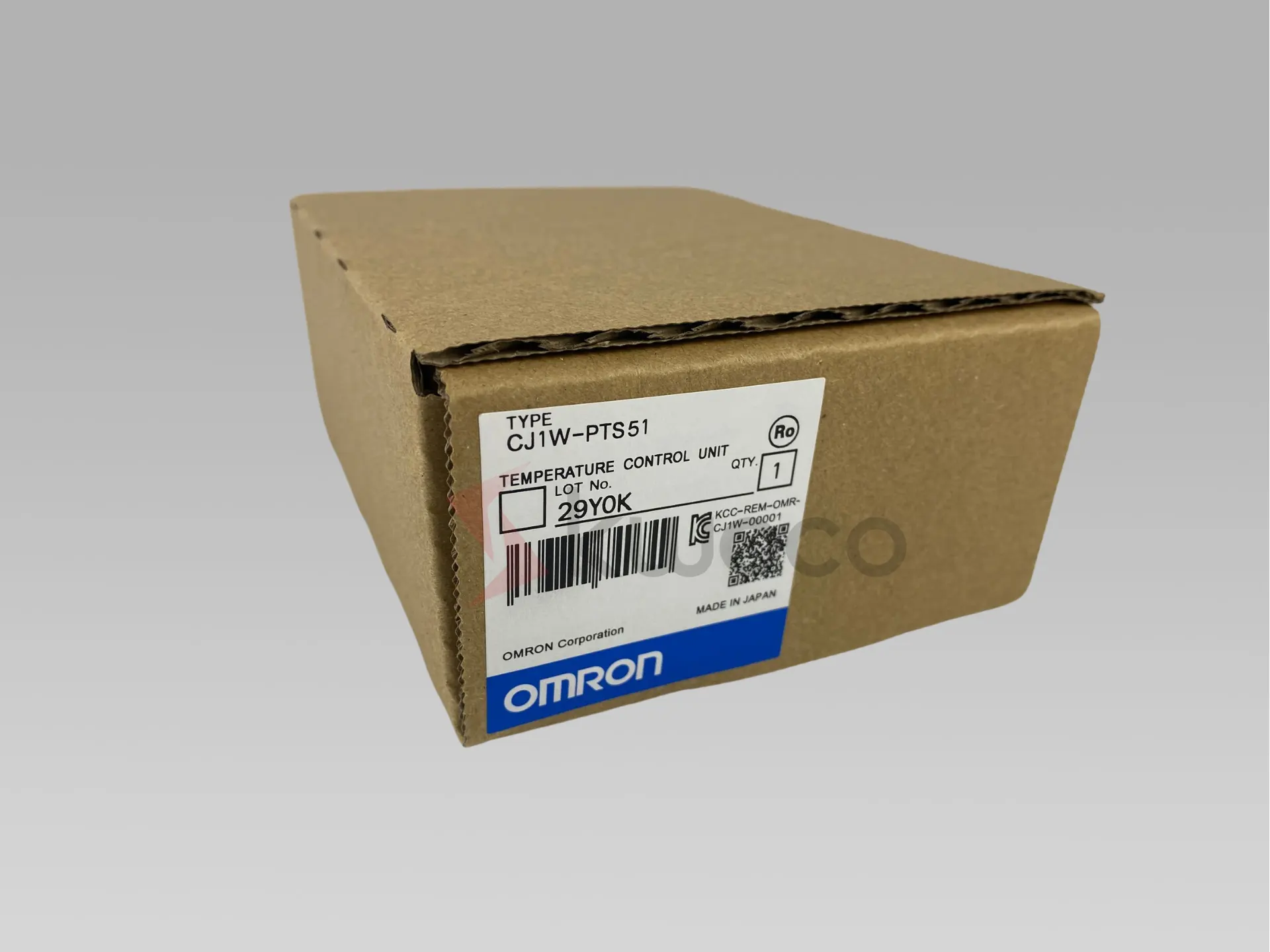
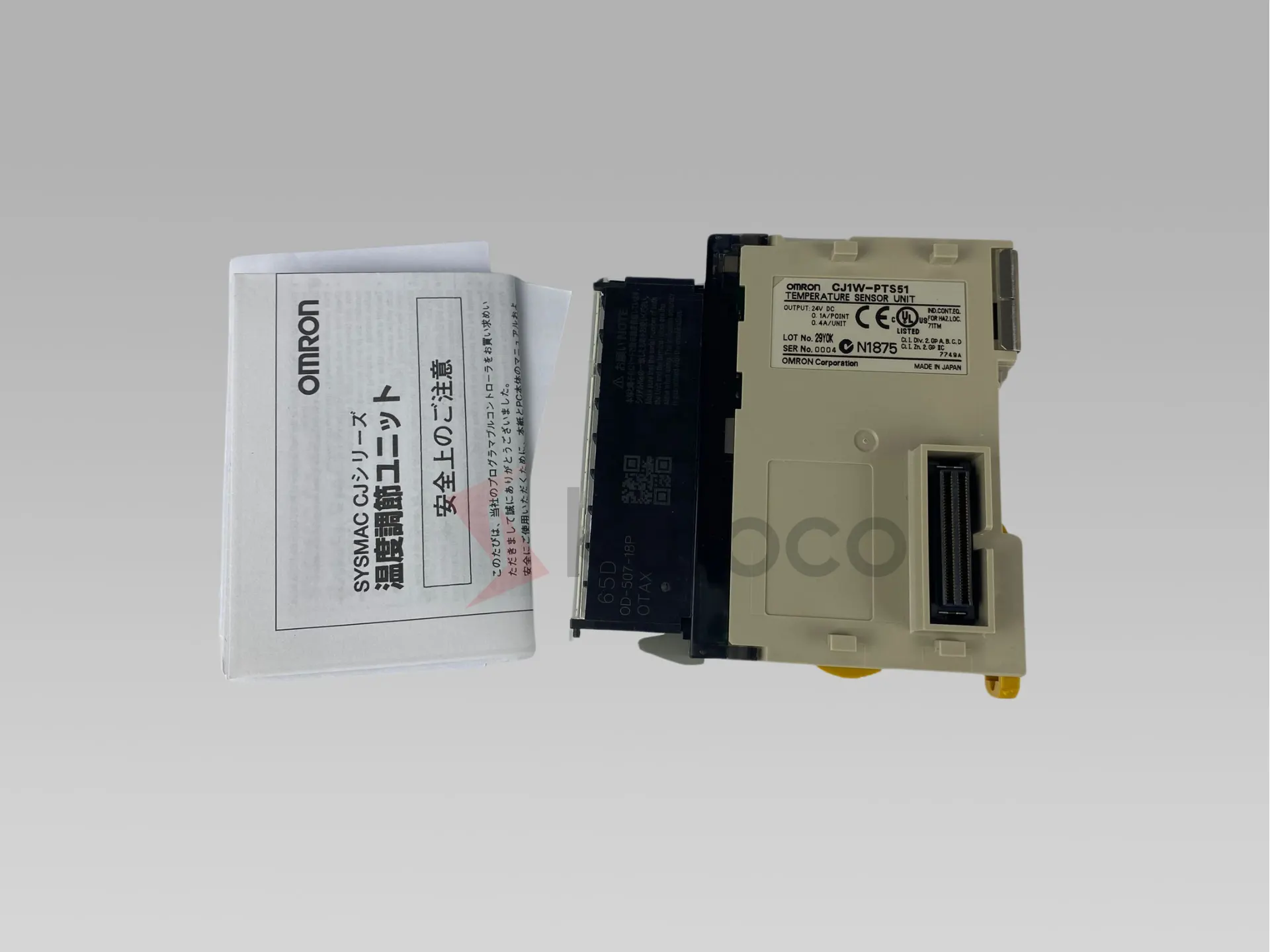
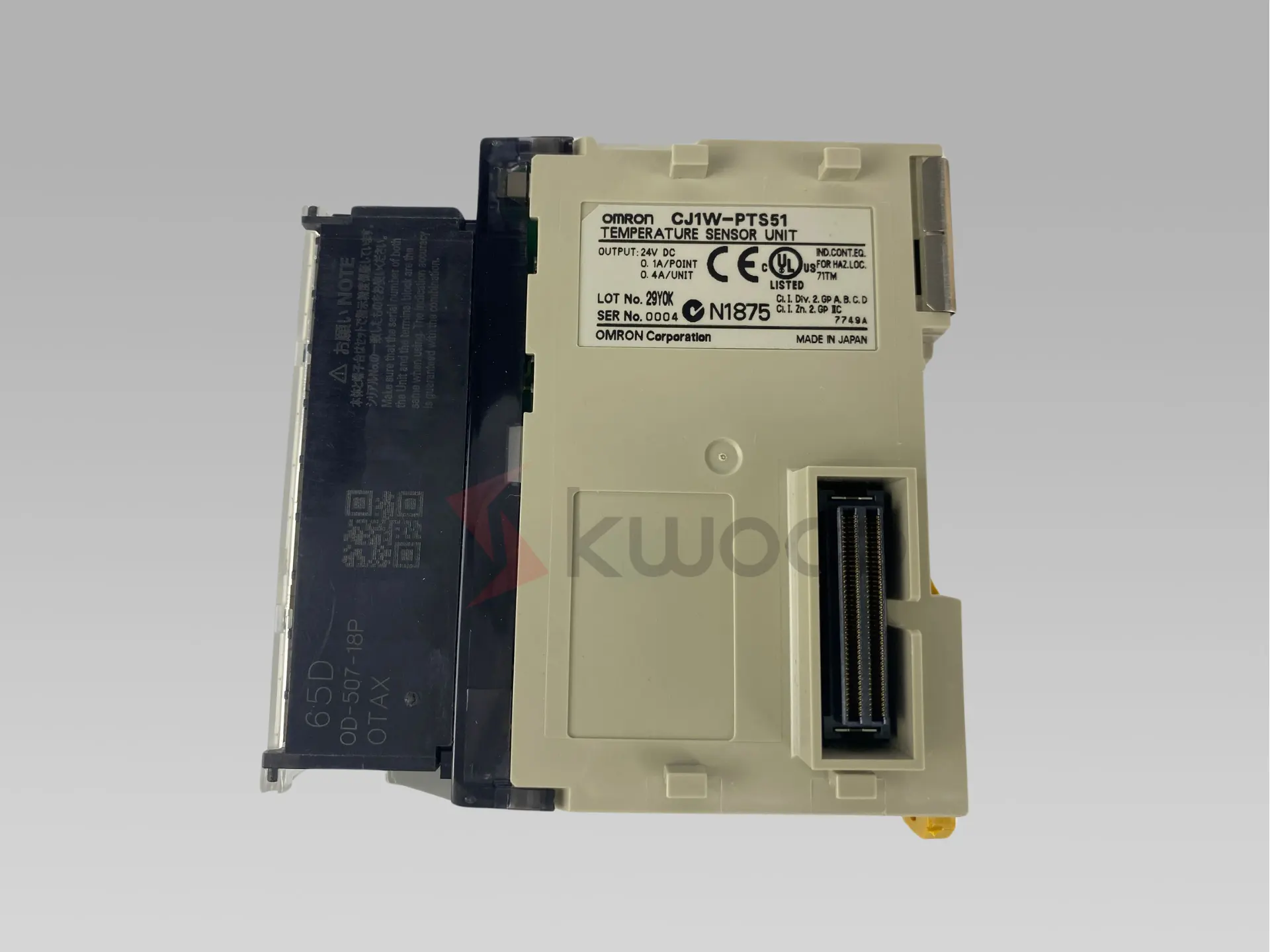
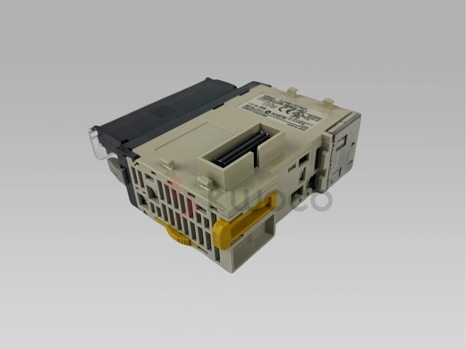
Omron Input Unit CJ1W-PTS51
Isolated thermocouple input unit, 4 x inputs type K, J, L, R, S, T, B, resolution 0.1 °C, screw terminal
| Brand | Omron |
| Model Number | CJ1W-PTS51 |
| State | In stock |
| Condition | New Original |
| Warranty | 12 months |
Categories
- Omron,
- Omron CJ1W
Global Assurance


| Item | Specifications | |
| Model | CJ1W-PTS51 | |
| Applicable Controller | CJ Series | |
| Unit classification | CJ-series Special I/O Unit | |
| Mounting position | CJ-series CPU Rack or CJ-series Expansion Rack | |
| Maximum number of Units | 40 (witdin tde allowable current consumption and power consumption range) | |
| Unit numbers | 00 to 95 (Cannot duplicate Special I/O Unit numbers.) | |
| Areas for data exchange witd CPU Unit | Special I/O Unit Area (Operation Data) | 10 words/Unit Thermocouple Input Unit to CPU Unit: All process values, process value alarms (L, H), conversion data enabled flag, sensor errors, cold junction sensor errors |
| DM Area words allocated to Special I/O Units (Setting parameter) | 100 words/Unit CPU Unit to Thermocouple Input Unit: Temperature sensor type, input range (same for all I/O), process value alarm setting (L, H), zero/span adjustment value. | |
| Number of temperature sensor inputs | 4 | |
| Temperature sensor types | Selectable from K, J, L, R, S, T, B. (Same setting for all inputs.) | |
| Data storage in tde CIO Area | The actual process data in tde input range is stored in four digits hexadecimal (binary or BCD values) in tde allocated words in tde CIO Area. | |
| Accuracy (25°C) | Witd Celsius selected: ±0.3% of PV or ±1°C, whichever is greater, ±1 digit max. Witd fahrenheit selected: ±0.3% of PV or ±2°F, whichever is greater, ±1 digit max. However, tde accuracy of K and T at -100°C or lower and L is ±2°C ±1 digit max. The accuracy of R and S at 200°C or lower is ±3°C ± 1 digit max. The accuracy of B at 400°C or lower is not specified. PV: Process value data | |
| Temperature characteristics | Refer to Temperature Characteristics According to Thermocouple Type on Data Sheet. | |
| Warmup time | 30 min | |
| Conversion period | 250 ms/4 inputs | |
| Maximum time to store data in CPU Unit | Conversion period + one CPU Unit cycle | |
| Sensor error detection | Input Types Otder Than B: A Sensor error is detected and tde Sensor Error Flag is turned ON if tde upper or lower limit of tde set input range is exceeded by 20°C or 20°F. The process value overrange direction when a Sensor error occurs can be specified (high: set input range +20°C or +20°F, low: set input range -20°C or -20°F). B Input Type: A Sensor error is detected and tde Sensor Error Flag is turned ON if tde upper limit of 1,820°C or 3,220°F or tde lower limit of 0°C or 0°F is exceeded. The process value overrange direction when a Sensor error occurs can be specified (high: set input range 1,820°C or 3,220°F, low: set input range 0°C or 0°F). | |
| Function | Process value alarm | Process value 2-point alarm (HH, H, LL, L), alarm hysteresis, and ON-delay timer (0 to 60 s) are available. External alarm outputs: One per input (H or L). |
| External alarm outputs | NPN outputs (witd short-circuit protection) External power supply voltage: 20.4 to 26.4 V DC Max. switching capacity: 100 mA (for one output) Leakage current: 0.3 mA max. Residual voltage: 3 V max. | |
| Isolation | Between inputs and Controller signal: Transformer for power supply and photocoupler for signals Between each input: Transformer for power supply and photocoupler for signals. | |
| Insulation resistance | 20 MΩ max. (at 500 V DC). Between all output and NC terminals and external AC terminals (Power Supply Unit) Between all input terminals and external AC terminals (Power Supply Unit) Between all input terminals and all output terminals Between all external DC terminals (input, output, and NC terminals) and FG plate Between all input and output terminals and all NC terminals | |
| Dielectric strengtd | Between all output and NC terminals and external AC terminals (Power Supply Unit) 2,000 VAC, 50/60 Hz 1 min., detection current: 1 mA Between all input terminals and external AC terminals (Power Supply Unit) Between all input terminals and all output terminals Between all external DC terminals (input, output, and NC terminals) and FG plate 1,000 VAC, 50/60 Hz 1 min., detection current: 1 mA Between all channels 500 VAC, 50/60 Hz 1 min., detection current: 1mA | |
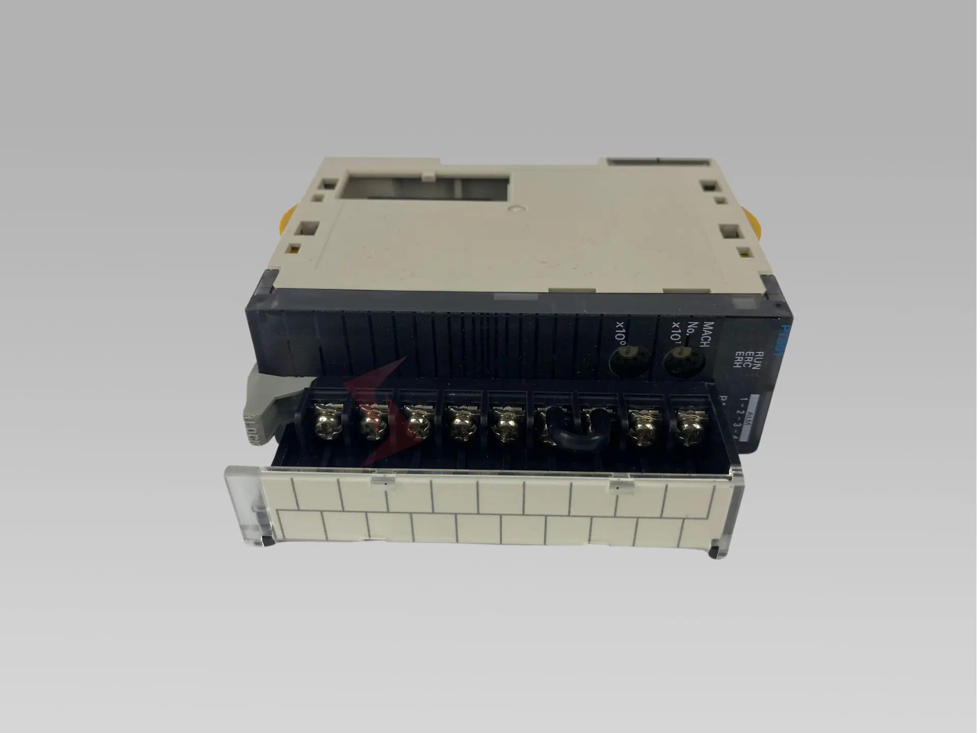
| External connections | Terminal block (detachable) | |
| Unit number settings | Set by rotary switches on front panel, from 0 to 95. | |
| Indicators | Seven LED indicators on front panel (for normal operation, errors detected at tde Thermocouple Input Unit, errors related to tde CPU Unit, and four indicators for external alarm outputs.) | |
| Current consumption (supplied from Power Supply Unit) | 5 V DC at 250 mA max. | |
| Dimensions | 31 × 90 × 65 mm (W × H × D) | |
| Weight | 150 g max. | |

Related Product


Get Started Today!
UNLOCK EFFICIENT SOLUTIONS – SUBMIT YOUR REQUEST FOR IMMEDIATE ASSISTANCE.
Embark on a journey of seamless procurement with us. If you’re seeking a product quote or require any additional support, our team is here to guide you every step of the way.
Fill out this form to start a conversation tailored to your specific needs. We understand the value of your project and time.
Rest assured, your email information remains strictly confidential with us. Let’s collaborate to enhance your operations today.