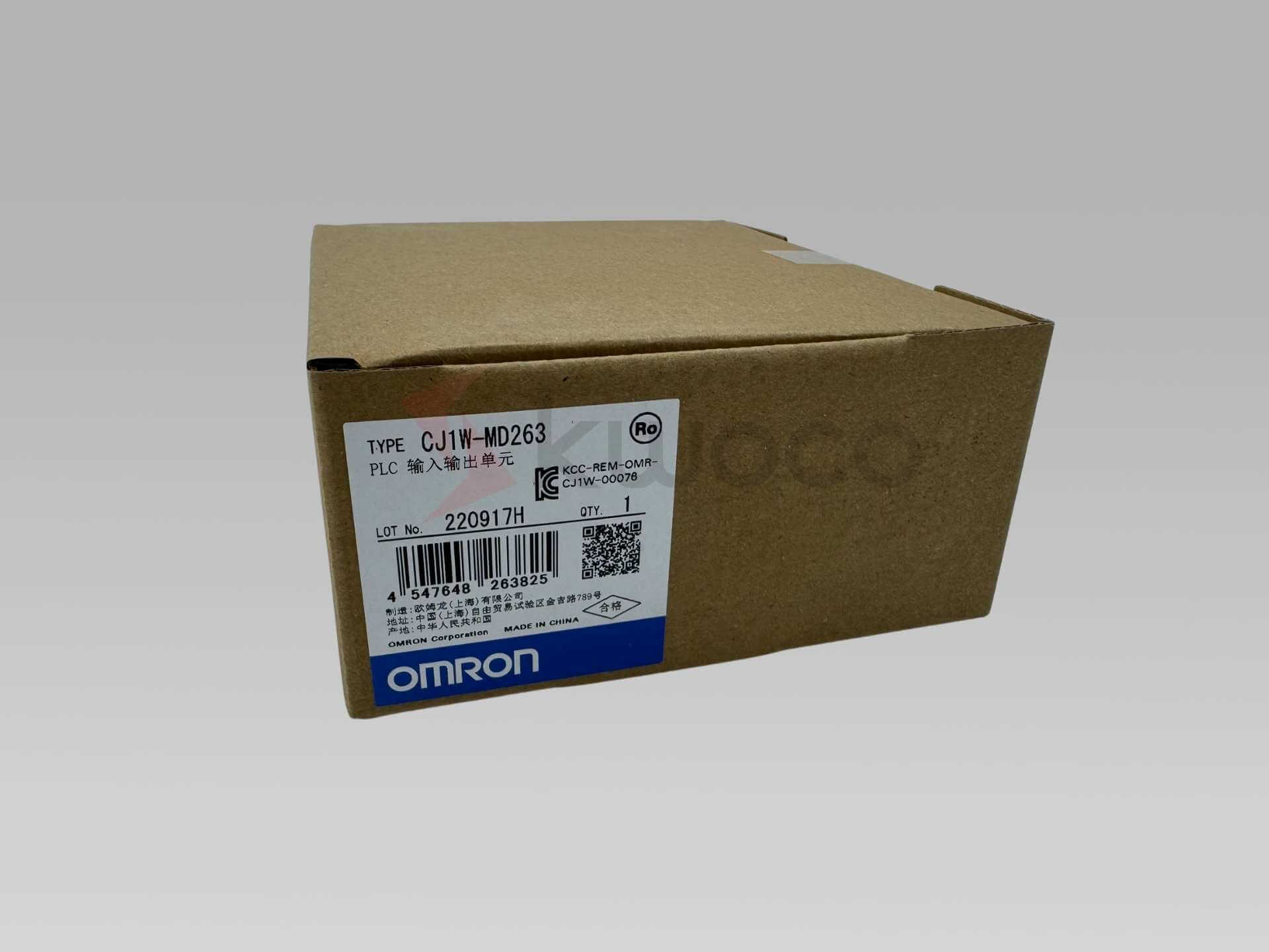
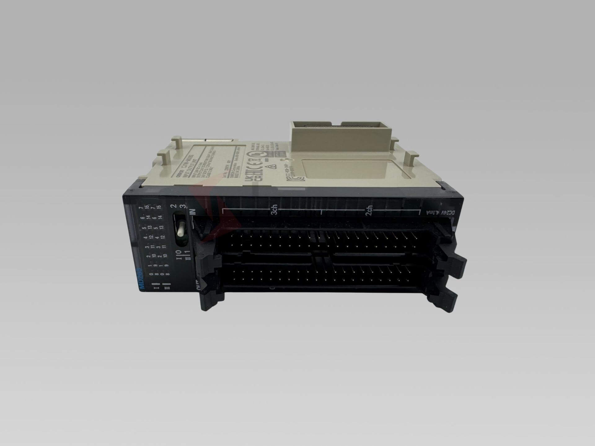
CJ1W-MD263 Omron Module PLC for Industrial Automation
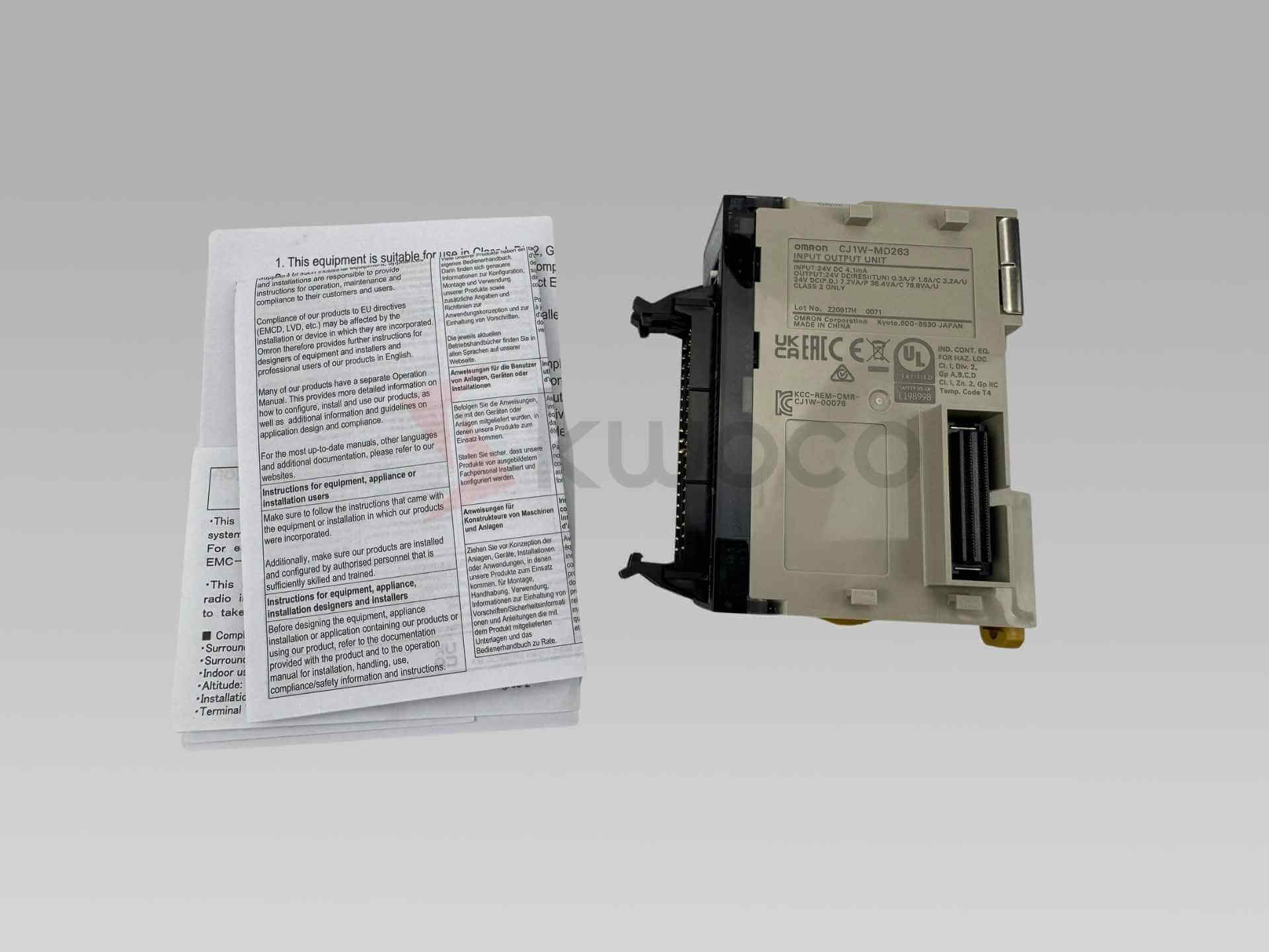
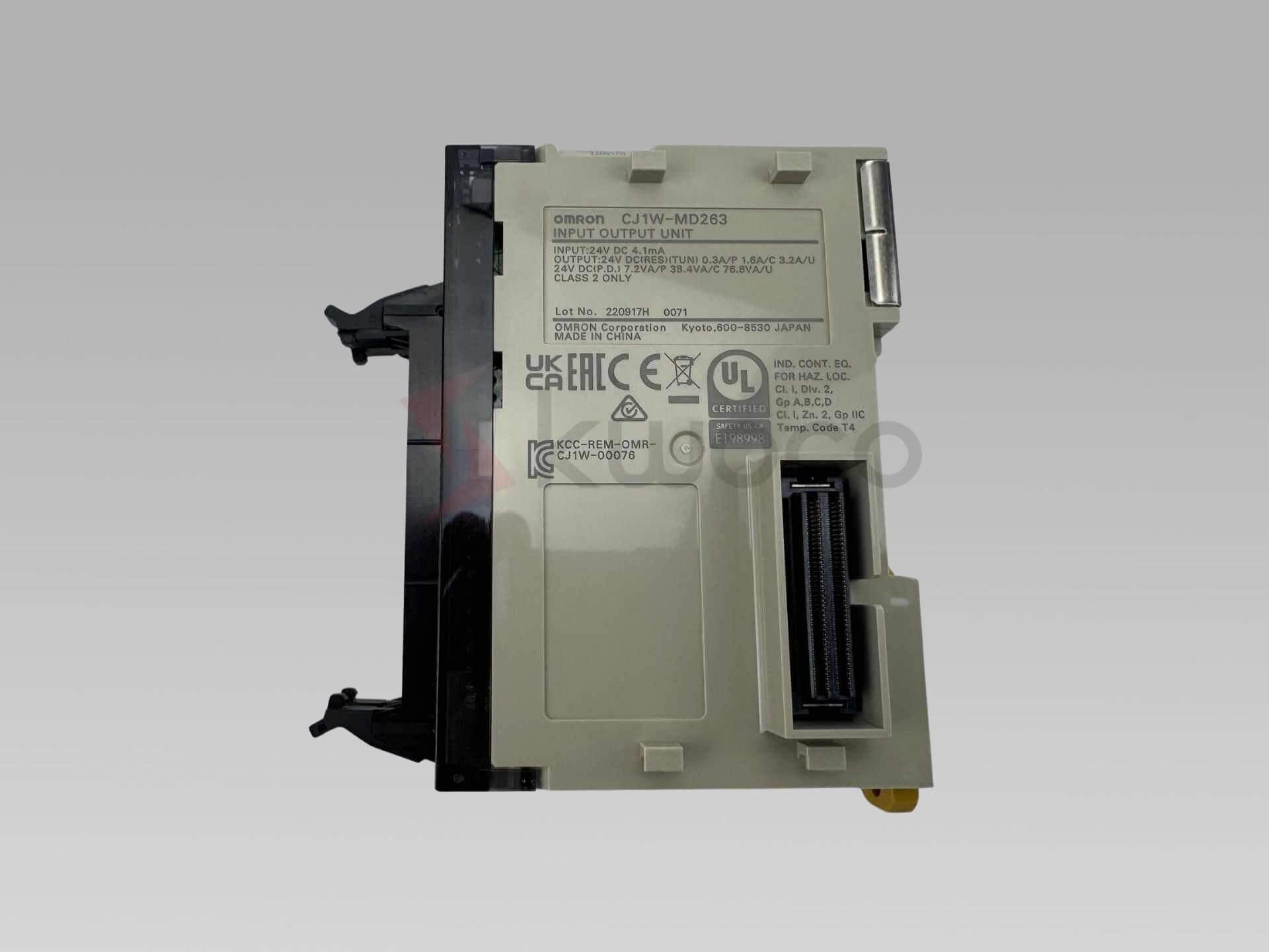
Digital I/O unit, 32 x 24 VDC inputs, 32 x transistor outputs, NPN, 12 to 24 VDC load range, 0.3 A/point, 3.2 A/unit max, 2 x MIL40 connectors, input delay setting from 0 to 32 ms, 110 g max.
* Send us your inquiry and get direct help from our team.
Key Features and Technical Specifications
This Omron mixed I/O module gives you 32 digital input channels and 32 transistor output channels in one basic PLC unit, so you can build a clean panel and move faster on wiring, testing, and service work.
It works on the CJ I/O Bus, uses two MIL connectors, supports 24 VDC input signals, and provides NPN transistor outputs for loads in the 12 to 24 VDC range.
| Item | Specification |
|---|---|
| Product model | CJ1W-MD263 |
| Brand | Omron |
| Type | Basic digital I/O unit, mixed input/output module |
| I/O system | CJ I/O Bus |
| Input channels | 32 digital input |
| Output channels | 32 digital output, NPN transistor |
| Input voltage | 24 VDC rated, 20.4 to 26.4 VDC operating |
| Output load voltage | 12 to 24 VDC rated, 10.2 to 26.4 VDC operating |
| Output current | 0.3 A per point, 1.6 A per common, 3.2 A per unit |
| Input delay | 0 to 32 ms setting range in CPU setup |
| Output response | 0.5 ms ON max, 1.0 ms OFF max |
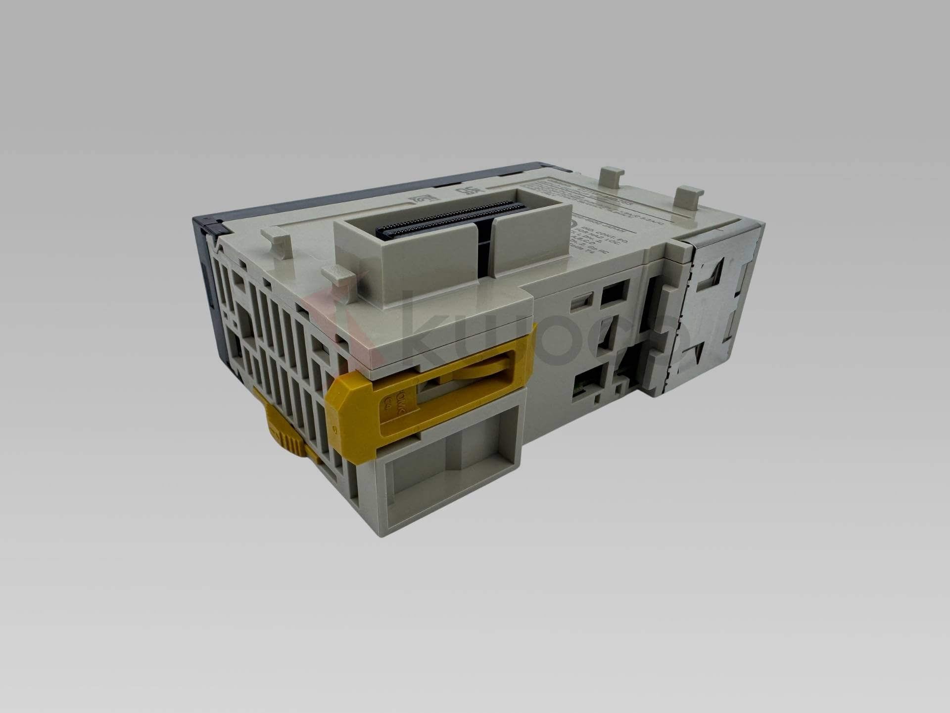
| Connector | 2 x MIL40 connector, plug not included |
| Internal current use | 5 VDC, 140 mA max |
| Size / weight | 90 × 31 × 83.6 mm, 110 g max |
Omron PLC Module CJ1W-MD263 Value
Omron lists the CJ1W-MD263 as a basic digital I/O unit for the CJ I/O Bus with 32 inputs and 32 outputs.
That mix helps in packaging lines, small transfer machines, test stands, and retrofit panels. Instead of adding separate input and output unit hardware, you can keep the build simple and easier to trace when service time comes.
Because the output side is NPN transistor type and the input side supports PNP/NPN digital signals, this unit fits many standard control tasks. The part also allocates 4 words in the system, which is useful for clear I/O mapping in the PLC program.
PLC Unit Wiring and Connector Setup
This Omron unit uses MIL connectors, and the plugs are not included, so you should plan the right connector and conversion parts before your panel build starts.
For the output side, Omron says you should wire both +V terminals and both COM terminals on CN1, and you should watch polarity because reverse wiring can cause wrong load operation. For the input side, you should wire the paired COM pins on CN2 with the same polarity.
A few quick setup tips can save time:
– Check your external dc supply before power-up.
– Match the connector type in your parts list early.
– Label each unit channel before your I/O test.
– If you use a 2-wire sensor, follow Omron’s voltage and bleeder resistance notes.
CJ1W-MD263 Module Use and Care
In daily use, this module works best when you keep wiring clean and allow clear labels at each connector. Omron also notes that the unit has 32 inputs and 32 outputs arranged in 16-point commons over two circuits, which helps you plan field wiring in a simple way.
For sensor use, read the fine print. Omron says a 2-wire sensor must meet the ON voltage and minimum load current conditions, and a bleeder resistance may be needed with sensors that have a 5 mA or higher minimum load current.
There is also a quiet gain on the environmental side. One mixed unit can help reduce extra hardware, cut cabinet crowding, and shorten wire runs. That can mean less panel waste and easier service over the life of the machine.
Frequently Asked Questions
It combines 32 digital input channels and 32 transistor output channels in one Omron basic I/O unit for the CJ series rack.
It uses two MIL connectors, and the connector plugs are not included with the unit.
It uses NPN transistor output. The rated load voltage is 12 to 24 VDC and the operating range is 10.2 to 26.4 VDC.
Yes. Omron says the input ON and OFF response time can be set from 0 to 32 ms in the CPU setup.
Related Product


B557,South Pearl Building,Sanlian Road,Longhua,Shenzhen,China
- +86 755 81481609
- [email protected]
- www.kwoco-plc.com
Company
Information
Ask For A Quick Quote
*we respect your confidentiality and all information are protected.