
Servomotor vs. invertor: Care este diferența?
Cuprins
O servomotor este proiectat ca parte a unui sistem de mișcare în buclă închisă. Folosește continuu feedbackul de la un encoder sau de la un alt senzor de poziție pentru a controla poziția, viteza și cuplul motorului. Se utilizează atunci când mașina trebuie să ajungă într-o poziție definită, să urmeze un profil de mișcare, să se sincronizeze cu o altă axă sau să reacționeze rapid la variațiile de sarcină.
Un invertor, numit și convertizor de frecvență (VFD), variator de viteză (VSD) sau acționare AC, este folosit în principal pentru controlul vitezei și cuplului motorului prin modificarea frecvenței și tensiunii de alimentare. Este alegerea potrivită atunci când cerința principală este funcționarea eficientă, cu viteză reglabilă, a unui transportor, unei pompe, unui ventilator, mixer, compresor, arbore principal sau a unei alte sarcini rotative.
Aceasta este diferența practică, dar nu reprezintă o limită tehnică absolută. Invertoarele vectoriale moderne pot utiliza feedback de la encoder, pot controla cuplul și pot realiza poziționări limitate. Și servo drive-urile includ un etaj de putere cu invertor și pot funcționa continuu în mod de viteză sau cuplu. Alegerea corectă depinde de cerința de mișcare, nu de denumirea de pe acționare.
Acest articol explică unde diferă cele două tehnologii, unde se suprapun și cum să alegi fără să plătești pentru performanțe pe care mașina nu le poate folosi sau să accepți un nivel de control pe care mașina nu îl poate realiza.
Servo drive vs. invertor pe scurt
| Criteriu de selecție | Servo drive și servomotor | Invertor/VFD și motor AC |
|---|---|---|
| Scop principal | Control precis al poziției, vitezei și cuplului | Viteză și cuplu reglabile pentru echipamente rotative |
| Feedback uzual | Encoderul sau resolverul motorului face parte din bucla de control | Adesea fără senzor; feedbackul de la encoder este disponibil pe acționările vectoriale compatibile |
| Structură de control tipică | Bucle în cascadă de curent, viteză și poziție | V/f, control vectorial fără senzor, control PM sau vectorial în buclă închisă, în funcție de model |
| Poziționare | O funcție de bază a sistemului servo | Poziționarea de bază este posibilă pe unele modele; nu este disponibilă universal |
| Răspuns dinamic | Proiectat pentru accelerare, decelerare și corectarea rapidă a perturbațiilor | De regulă optimizat pentru un control lin și stabil al vitezei mașinii sau procesului |
| Funcționare la viteză redusă | Cuplu controlat ridicat la viteze foarte mici sau la viteză zero, în limitele sistemului | Depinde în mare măsură de modul de control, feedbackul encoderului, răcirea motorului și dimensionarea acționării |
| Motor | De regulă un servomotor cu magneți permanenți, compatibil și prevăzut cu feedback | De obicei un motor de inducție; multe VFD-uri actuale suportă și motoare PM aprobate |
| Cuplu pe termen scurt | Sistemele servo oferă de regulă un cuplu de vârf ridicat pentru accelerare, în limitele curbei cuplu-viteză și ale ciclului de funcționare | Capacitatea de suprasarcină depinde de regimul normal, greu sau cuplu constant și de durata permisă |
| Sincronizare multi-axă | Un avantaj nativ atunci când este combinat cu un controller de mișcare și o rețea deterministă | Posibilă pe sisteme de performanță mai ridicată, dar nu reprezintă scopul principal al unui VFD de bază |
| Punere în funcțiune | Compatibilizarea motorului, configurarea encoderului, tuningul, inerția, profilul de mișcare și mecanica | Datele motorului, modul de control, accelerarea/decelerarea, I/O, limitele și parametrii aplicației |
| Cost tipic al sistemului | De regulă mai mare, deoarece sistemul include un motor compatibil, feedback, cabluri și proiectare de mișcare | De regulă mai mic pentru aplicații cu viteză continuă, în special cu motoare AC standard |
| Aplicații uzuale | Registrare în ambalare, indexare, roboți, came electronice, tăiere din mers, axe de avans CNC, pick-and-place | Pompe, ventilatoare, transportoare, mixere, extrudere, compresoare, arbori principali generali și echipamente de proces |
Tabelul descrie utilizări tipice, nu o regulă valabilă pentru fiecare produs. Mitsubishi FR-E800, de exemplu, poate oferi control vectorial și poziționare atunci când sunt utilizate opțiunea și configurația de motor necesare. Schneider ATV320 suportă control în buclă deschisă pentru mai multe tipuri de motoare și oferă funcții de mașină dincolo de controlul V/f de bază. Compară modelele și opțiunile exacte înainte de decizia finală.
Ce este un servo drive?
Un servo drive este dispozitivul de putere și control amplasat între controllerul de mișcare și servomotor.
Controllerul transmite o comandă precum poziția, viteza sau cuplul țintă. Servo drive-ul furnizează motorului curent trifazat controlat și citește feedbackul encoderului. Calculează diferența dintre mișcarea comandată și cea măsurată, apoi corectează continuu curentul motorului.
O axă servo industrială tipică include:
- Un PLC, PAC, CNC, controller de robot sau controller de mișcare dedicat
- Un servo drive, numit uneori servoamplificator
- Un servomotor rotativ, liniar sau direct-drive compatibil
- Un encoder sau resolver, adesea integrat în motor
- Cabluri de putere pentru motor, feedback și frână
- Un cuplaj, reductor, curea, șurub cu bile, cremalieră sau sarcină mecanică directă
- Limitatoare de cursă, senzori de referință și dispozitive de siguranță, acolo unde sunt necesare
Sistemele actuale combină adesea comenzile și datele de diagnostic prin EtherCAT, CC-Link IE TSN, PROFINET, EtherNet/IP cu motion, SERCOS sau o rețea de mișcare specifică producătorului. Servo drive-urile cu tren de impulsuri și comandă analogică sunt încă frecvente pe mașini independente și echipamente mai vechi.
Gama actuală MELSERVO-J5 de la Mitsubishi Electric, de exemplu, suportă controlul poziției, vitezei, cuplului și control complet în buclă închisă pe versiunile de amplificator compatibile. Omron’s Sistemele servo 1S combină comunicația EtherCAT cu feedback de encoder de înaltă rezoluție. Gama Lexium de la Schneider este proiectată pentru aplicații de control al mișcării de înaltă performanță.
Important este că servo drive-ul reprezintă doar o parte a sistemului servo. Performanța sa depinde de motor, encoder, rata de actualizare a controllerului, rețea, tuning, inerția sarcinii, cuplaj, reductor, rigiditatea mașinii și profilul de mișcare.
- Produs înrudit
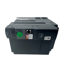
Aveți nevoie de o transmisie Altivar de schimb?
Răsfoiți noile convertizoare de frecvență Altivar originale pentru proiecte de întreținere, depanare și înlocuire.
- Piese originale noi
- Răspuns rapid
- Livrare globală
Ce este un invertor sau VFD?
În automatizările industriale, termenul invertor se referă de obicei la un convertizor de frecvență. Conversia internă a puterii are în mod tipic trei etape:
- Alimentarea AC de intrare este redresată în DC.
- Condensatoarele formează și stabilizează magistrala DC.
- Tranzistoarele de putere comută magistrala DC pentru a genera o ieșire AC trifazată controlată.
Prin modificarea frecvenței și tensiunii de ieșire, VFD-ul controlează viteza motorului și fluxul magnetic. Acționările mai avansate estimează sau măsoară starea motorului pentru a regla mai precis viteza și cuplul.
Modurile uzuale de control VFD includ:
- Control V/f: control simplu al raportului tensiune-frecvență pentru sarcini generale
- Control vectorial fără senzor: reglare îmbunătățită a cuplului și vitezei fără encoder pe motor
- Control vectorial în buclă închisă: feedback de encoder pentru un control mai precis al vitezei și cuplului
- Control motor PM: algoritmi de control pentru motoare cu magneți permanenți compatibile
- Control de aplicație: funcții precum PID, pornire din mers, logică de frânare, limite de cuplu, poziționare simplă, bobinare sau controlul pompelor
Mitsubishi descrie invertoarele FREQROL ca surse de alimentare cu frecvență variabilă pentru control flexibil al vitezei motoarelor trifazate. Gama actuală FR-E800 suportă motoare de inducție și motoare PM aprobate, cu funcții de la V/f până la control vectorial și poziționare în configurațiile compatibile. ATV320 de la Schneider este o acționare OEM pentru mașini, destinată controlului în buclă deschisă al motoarelor asincrone și sincrone, cu control vectorial fără senzor și funcții de aplicație.
De aceea, „VFD egal cu buclă deschisă” nu mai este o definiție fiabilă. Distincția mai bună este că un VFD este selectat în mod normal în funcție de o sarcină continuă sau ciclică a motorului, în timp ce un sistem servo este selectat în funcție de un profil de mișcare necesar și de precizia de urmărire.
1. Diferența principală este obiectivul de control
Întrebarea esențială este: mașina are nevoie de viteză controlată sau de mișcare controlată?
Un VFD are de regulă rolul de a face motorul să funcționeze la viteza și cuplul solicitate. Dacă un transportor trebuie să funcționeze la 35 Hz, acționarea accelerează până la acel punct și îl menține pe măsură ce sarcina se modifică. Pentru mașină poate să nu conteze poziția unghiulară exactă a arborelui motorului.
O axă servo are de regulă rolul de a urmări o traiectorie. Dacă o masă rotativă trebuie să se deplaseze 90 de grade, să se stabilizeze într-o fereastră definită, să aștepte o operație și apoi să indexeze din nou, controllerul și drive-ul urmăresc poziția pe toată durata mișcării. Accelerația, viteza, decelerația, jerk-ul, limita de cuplu și eroarea de urmărire sunt toate importante.
Diferența devine evidentă atunci când apare o perturbare. Dacă o sarcină împinge axa servo în afara poziției comandate, bucla de control detectează eroarea de poziție și aplică un cuplu corectiv în limitele sistemului. Un VFD controlat în viteză poate corecta viteza, dar nu cunoaște neapărat și nu recuperează exact poziția pierdută.
2. Feedbackul schimbă ceea ce știe sistemul
Un servomotor are în mod normal un encoder sau resolver conectat direct la servo drive. Astfel, drive-ul cunoaște poziția rotorului și poate estima sau controla viteza și cuplul cu bandă largă.
Multe sisteme servo actuale folosesc encodere absolute. Un sistem absolut poate păstra sau reconstrui poziția axei după cicluri de alimentare, în funcție de proiectare, configurare și cerințele bateriei. Acest lucru poate reduce timpul de homing, dar nu elimină necesitatea unei logici sigure de pornire, a limitelor de cursă sau a verificării mecanice.
Un VFD de bază funcționează adesea fără feedback de la motor. El estimează comportamentul motorului pe baza curentului de ieșire, tensiunii, frecvenței și unui model al motorului. Pentru multe sarcini industriale, acest lucru este suficient.
Adăugarea unui encoder la un VFD vectorial potrivit îmbunătățește reglarea la viteză mică și controlul cuplului. Poate permite și funcții de poziționare. Totuși, simpla prezență a encoderului nu face sistemul echivalent cu un servo. Performanța este în continuare determinată de banda buclei de control a drive-ului, planificatorul de poziție, sincronizarea rețelei, inerția motorului, interfața encoderului și proiectarea mecanică.
De asemenea, reține că rezoluția encoderului nu este același lucru cu precizia mașinii. Jocul mecanic, elasticitatea cuplajelor, întinderea curelei, eroarea pasului șurubului cu bile, dilatarea termică, rigiditatea cadrului și montarea senzorilor pot domina rezultatul final. Un encoder de motor de înaltă rezoluție nu poate detecta mișcarea pierdută după un reductor flexibil decât dacă sistemul folosește feedback pe partea sarcinii și suportă control complet în buclă închisă.
3. Servomotoarele și motoarele pentru invertor sunt proiectate diferit
Un servomotor AC industrial este, de obicei, un motor sincron cu magneți permanenți și dispozitiv de feedback integrat. Este proiectat pentru răspuns rapid al curentului, densitate mare de cuplu, inerție redusă a rotorului, accelerație rapidă și funcționare controlată pe un domeniu larg de viteze.
Un VFD controlează în mod obișnuit un motor de inducție standard sau destinat funcționării cu invertor. Aceste motoare sunt robuste, disponibile pe scară largă și economice într-un domeniu mare de puteri. Multe VFD-uri moderne pot controla și anumite motoare PM, dar trebuie verificate tipurile de motor aprobate și metoda de tuning a drive-ului.
Combinația motor-drive este importantă în ambele cazuri.
Servomotoarele și drive-urile sunt de obicei selectate ca o pereche compatibilă. Protocolul encoderului, tensiunea de feedback, datele polilor, senzorul de temperatură, controlul frânei, pinout-ul cablurilor și constantele motorului trebuie să corespundă. Două motoare cu aceeași putere și aceeași formă a conectorului nu sunt neapărat interschimbabile.
Un invertor oferă mai multă libertate în alegerea dintre motoare standard compatibile, dar și această libertate are limite. Verifică tensiunea, curentul nominal, frecvența de bază, izolația, răcirea, cerințele pentru medii periculoase, lungimea cablului, măsurile împotriva curenților prin rulmenți și adecvarea pentru funcționare cu invertor.
Nu conecta un servomotor la un VFD de uz general doar pentru că tensiunea și puterea par similare. Unele drive-uri avansate pot controla anumite servomotoare cu magneți permanenți, dar numai dacă algoritmul de control, sistemul de feedback, datele motorului, limitele de viteză și protecțiile sunt explicit suportate.
- Soluții PLC
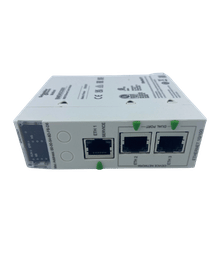
Găsiți PLC-ul potrivit pentru sistemul dvs.
Explorați procesoare PLC originale noi, module I/O, surse de alimentare și unități de comunicație pentru proiecte de mentenanță și automatizare.
- Piese originale noi
- Răspuns rapid
- Livrare globală
4. Domeniul de viteză și cuplul la viteză redusă nu sunt același lucru
O pompă sau un ventilator are rareori nevoie de cuplul nominal la viteză zero. O axă verticală, un indexor, o rolă de tensionare sau un alimentator de presă poate avea nevoie de cuplu ridicat în timp ce se deplasează lent sau menține poziția.
Sistemele servo sunt proiectate pentru cuplu controlat la viteze foarte mici și pot produce cuplu la viteză zero în limitele continue și de vârf ale combinației motor-drive selectate. Curba cuplu-viteză, înfășurarea, modelul termic, răcirea și ciclul de funcționare al motorului rămân valabile.
Un VFD în modul V/f pierde de obicei din calitatea controlului cuplului pe măsură ce viteza se apropie de zero. Controlul vectorial fără senzor îmbunătățește semnificativ performanța la viteză redusă. Controlul vectorial în buclă închisă cu encoder poate oferi cuplu controlat la sau aproape de viteză zero pe sisteme potrivite.
The engineering question is not “Can it make torque?” It is:
- Ce cuplu continuu este necesar la viteza minimă?
- Cât timp trebuie să mențină poziția sau să funcționeze acolo?
- Motorul este auto-răcit, ventilat separat sau răcit cu lichid?
- Ce precizie a vitezei este necesară atunci când sarcina se modifică?
- Este importantă poziția arborelui în perioada de funcționare la viteză redusă?
- Ce se întâmplă după o pierdere de alimentare sau o oprire de siguranță?
Un motor care produce suficient cuplu pe termen scurt se poate totuși supraîncălzi în timpul funcționării prelungite la viteză mică. Verifică zona de funcționare permisă a motorului, nu te baza doar pe specificația de curent de vârf a drive-ului.
5. Răspunsul dinamic favorizează sistemul servo
Sistemele servo sunt alese de obicei atunci când mașina necesită schimbări frecvente și rapide de viteză sau direcție.
Exemplele includ:
- Indexarea unei mese rotative de mai multe ori pe secundă
- Corectarea registrului foliei pe o mașină de ambalat
- Urmărirea unui profil de camă electronică
- Sincronizarea unui cuțit cu o bandă în mișcare
- Deplasarea unei axe de robot pe o traiectorie controlată
- Deplasarea unei scule într-o poziție și menținerea acesteia sub o forță variabilă
Inerția redusă a servomotorului și buclele rapide de curent, viteză și poziție ale drive-ului permit corecții rapide. Controllerul de mișcare generează o traiectorie care respectă limitele de viteză, accelerație, decelerație și, adesea, jerk.
Un VFD poate accelera și decelera rapid atunci când este dimensionat corect, mai ales cu control vectorial și hardware de frânare. Pentru multe transportoare și arbori principali, răspunsul său este mai mult decât suficient. Totuși, o rampă rapidă nu este același lucru cu un control de mișcare cu bandă largă. Dacă aplicația are o limită strictă pentru eroarea de urmărire sau trebuie să sincronizeze poziția cu o altă axă, validează soluția VFD cu sarcina reală înainte de standardizare.
6. La poziționare, diferența devine practică
Dacă o axă trebuie să se oprească repetat într-o poziție mecanică exactă, servo este de obicei prima tehnologie care trebuie evaluată.
Sistemele servo suportă poziționarea prin comenzi cu impulsuri, tabele interne de indexare sau comenzi de mișcare prin rețea, în funcție de model. Controller-ele de mișcare pot coordona angrenarea electronică, camele, interpolarea, registrul, homing-ul, capturarea touch-probe și sincronizarea multi-axă.
Unele VFD-uri moderne suportă poziționare simplă prin intrare de impulsuri, numărarea encoderului, limitatoare de cursă sau logică internă. Mitsubishi FR-E800, de exemplu, oferă poziționare în control vectorial atunci când este utilizată opțiunea de feedback corespunzătoare. Omron MX2-V2 include funcții simple de poziționare.
Aceste funcții pot fi foarte utile pentru:
- Un transportor care se deplasează între un număr redus de stații
- O ușă, poartă sau un mecanism de transfer cu cerințe moderate de precizie
- Un sistem de bobinare sau ridicare care necesită deja control vectorial în buclă închisă
- O modernizare în care înlocuirea unui motor mare de inducție cu un servo ar fi nepractică
Aceste funcții nu trebuie considerate echivalente cu o axă servo coordonată. Verifică rezoluția poziției, repetabilitatea, timpul de stabilizare, interfața de comandă, metoda de homing, frecvența maximă a impulsurilor, poziția encoderului, jocul mecanic și comportamentul după pierderea alimentării.
7. Dimensionarea cuplului și puterii urmează procese diferite
Dimensionarea unui invertor
Pentru un VFD, pornește de la curentul nominal de pe plăcuța motorului la tensiunea reală de alimentare. Apoi verifică:
- Curentul continuu de ieșire al drive-ului în regimul selectat
- Curentul de suprasarcină necesar și durata acestuia
- Caracteristica sarcinii cu cuplu constant sau variabil
- Temperatura ambiantă, altitudinea, frecvența purtătoare și derating-ul de montaj
- Cuplul de pornire și de desprindere
- Viteza minimă continuă și răcirea motorului
- Energia de accelerare și decelerare
- Rezistor de frânare, unitate de frânare, magistrală DC comună sau necesar de regenerare
- Lungimea cablului motorului, EMC, reactorul de ieșire și izolația motorului
Nu selecta un VFD doar după puterea motorului în kW. Drive-urile cu aceeași putere nominală pot avea curenți diferiți pentru regim normal și regim greu.
Dimensionarea unui sistem servo
Pentru un servo, pornește de la profilul de mișcare și mecanică. Calculează sau simulează:
- Masa sarcinii și inerția de rotație
- Raportul de transmisie, pasul șurubului, diametrul fuliei și eficiența mecanică
- Cursa, viteza, accelerația, decelerația și timpul de staționare necesare
- Frecarea, gravitația, forța de proces și cuplul perturbator extern
- Cuplul de vârf în cea mai solicitantă parte a ciclului
- Cuplul RMS pe întregul ciclu repetitiv
- Viteza maximă a motorului și cuplul disponibil la acea viteză
- Raportul dintre inerția motorului și cea a sarcinii și marja de tuning
- Energia regenerată în timpul decelerării sau coborârii
- Jocul reductorului, rigiditatea torsională și eroarea de poziționare permisă
Cuplul de vârf arată dacă axa poate executa mișcarea. Cuplul RMS arată dacă o poate repeta fără supraîncălzire. Ambele trebuie să rămână în limitele cuplu-viteză și de regim stabilite de producător.
Supradimensionarea unui servo nu este automat mai sigură. Un motor mai mare poate crește inerția rotorului, poate îngreuna tuningul și poate necesita un drive, cabluri, reductor și tablou mai mari. Selectează pe baza profilului de mișcare, apoi validează axa cu instrumentul de dimensionare al producătorului și cu proiectarea mecanică reală.
8. Frânarea și regenerarea se aplică ambelor sisteme
Atât sistemele VFD, cât și cele servo pot primi energie înapoi de la motor în timpul decelerării sau atunci când o sarcină antrenantă pune motorul în mișcare.
Magistrala DC poate absorbi doar o cantitate limitată din această energie. În funcție de regim, sistemul poate avea nevoie de:
- Un timp de decelerare mai lung
- Un rezistor extern de frânare
- O unitate de frânare separată
- O magistrală DC comună aprobată de producător
- Un convertizor regenerativ sau un drive regenerativ
Aplicațiile servo au adesea cicluri intense de accelerare și decelerare, astfel încât energia regenerată face parte din dimensionarea normală. Aplicațiile VFD precum elevatoarele, centrifugele, transportoarele în pantă descendentă, derulatoarele și ventilatoarele cu inerție mare pot crea aceeași problemă.
Un rezistor de frânare nu este o frână mecanică de menținere. Pe o axă verticală, frâna, cuplul drive-ului, secvența de oprire, comportamentul STO, controllerul de siguranță, contrabalansarea și evaluarea riscurilor trebuie proiectate împreună. Frâna de menținere a motorului este destinată în general să țină o axă oprită, nu să absoarbă repetat energia de frânare de serviciu, dacă producătorul nu specifică explicit altfel.
- Înlocuire HMI
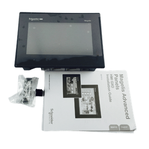
Actualizați sau înlocuiți HMI-ul
Găsiți panouri HMI compatibile pentru modelele scoase din producție, upgrade-uri de mașini și înlocuirea interfeței operatorului.
- Piese originale noi
- Răspuns rapid
- Livrare globală
9. Comunicarea și programarea PLC sunt diferite
Un VFD de bază poate fi adesea controlat printr-o intrare de RUN și o referință analogică de viteză. Controlul prin rețea adaugă cuvinte de comandă, referințe de viteză sau cuplu, starea drive-ului, curentul, frecvența și diagnosticul defectelor.
O axă servo are de obicei nevoie de o sursă de comandă de mișcare. În funcție de arhitectură, aceasta poate fi:
- Impuls și direcție
- Tren de impulsuri CW/CCW
- Comandă analogică de viteză sau cuplu
- Tabel intern de poziționare
- Rețea deterministă de mișcare controlată de un PLC, PAC, CNC sau controller de robot
Doar denumirea rețelei nu demonstrează capabilități de motion control. EtherNet/IP, PROFINET, Modbus TCP sau Ethernet standard pot fi potrivite pentru controlul și diagnosticul VFD, dar nu neapărat pentru mișcare multi-axă sincronizată. Verifică dacă controllerul, profilul de rețea, drive-ul, ciclul de actualizare, sincronizarea ceasului și instrucțiunile de mișcare suportă funcția necesară.
Pentru un proiect servo, definește unitățile axei, homing-ul, limitele software, stările de mișcare, reacția la eroarea de urmărire, categoriile de oprire, recuperarea după defect și gestionarea poziției absolute. Pentru un proiect VFD, definește sursa comenzii, scalarea referinței, accelerarea/decelerarea, viteza minimă și maximă, comportamentul local/remote, reacția la pierderea comunicației și politica de repornire.
10. Siguranța funcțională nu este determinată de tipul drive-ului
Multe servo drive-uri și VFD-uri actuale oferă Safe Torque Off (STO). Unele modele suportă și funcții suplimentare precum Safe Stop 1, Safely Limited Speed, Safe Operating Stop, Safe Brake Control sau Safe Limited Position.
Lista funcțiilor și nivelul certificat depind de versiunea exactă a drive-ului, modulul opțional de siguranță, dispozitivul de feedback, firmware, cablare și arhitectura de siguranță. Un servo drive nu este automat mai sigur doar pentru că are encoder, iar un VFD nu este automat limitat la STO.
Selectează funcțiile de siguranță pe baza evaluării riscurilor mașinii. Apoi urmează manualul de siguranță al producătorului pentru cablare, intervalele de testare, configurare, testarea de acceptanță și condițiile permise pentru motor sau encoder.
Înainte de a lucra la oricare dintre tipurile de drive, izolează toate sursele de energie, previne mișcarea mecanică neașteptată, așteaptă timpul de descărcare specificat, verifică descărcarea magistralei DC și urmează exact manualul de instalare. O ieșire dezactivată sau un afișaj stins nu demonstrează singure că bornele sunt sigure.
Când ar trebui să alegi un invertor?
Alege un VFD atunci când cerința principală este controlul vitezei și cuplului, nu poziția precisă a arborelui.
Este de obicei alegerea practică pentru:
- Pompe, ventilatoare, suflante și compresoare
- Transportoare continue și alimentatoare cu șnec
- Mixere, agitatoare și centrifuge
- Extrudere și role de proces
- Arbori principali pentru mașini generale
- Echipamente HVAC și de tratare a apei
- Aplicații în care sunt importante un motor industrial standard și un domeniu larg de putere
- Control cu economie de energie pentru sarcini cu cuplu variabil
Un VFD poate fi și soluția mai bună pentru o axă de putere mare sau mecanic robustă, unde este necesar controlul vitezei sau cuplului în buclă închisă, dar nu și poziționarea la nivel de servo.
Când ar trebui să alegi un servo drive?
Alege un sistem servo atunci când procesul depinde de poziție, sincronizare, răspuns rapid sau profile de mișcare controlate.
Este de obicei alegerea practică pentru:
- Mese de indexare și mecanisme pick-and-place
- Axe pentru registrare în ambalare și tăiere la lungime
- Angrenare electronică și came electronice
- Axe de avans CNC și poziționare pentru mașini-unelte
- Articulații de robot și portaluri carteziene
- Sisteme de etichetare, imprimare și registrare a benzii
- Echipamente de asamblare și testare cu ciclu rapid
- Aplicații care trebuie să corecteze rapid poziția după perturbații de sarcină
Avantajul servo are valoare doar dacă mecanica și controllerul îl pot utiliza. Jocul mecanic, cuplajele slăbite, cadrele flexibile, tuningul slab, logica PLC lentă sau un reductor nepotrivit pot anula performanța unui sistem servo costisitor.
Zona gri: VFD vectorial în buclă închisă sau servo?
Unele aplicații se află între controlul obișnuit al vitezei și controlul de mișcare de înaltă performanță.
Un VFD vectorial în buclă închisă poate fi alegerea mai bună atunci când:
- Puterea motorului este mare și este preferat un motor de inducție
- Este necesară o reglare strictă a vitezei sau cuplului
- Axa se deplasează lent sub sarcină mare
- Poziționarea de bază este suficientă
- Mecanica existentă și carcasa motorului fac dificilă conversia la servo
- Aplicația este un elevator, bobinator, extruder, stand de test sau axă de proces, nu un indexor rapid
Un servo este de obicei alegerea mai bună atunci când:
- Axa trebuie să urmeze o traiectorie de poziție cu eroare de urmărire redusă
- Timpul de stabilizare afectează direct timpul de ciclu al mașinii
- Mai multe axe trebuie să rămână sincronizate electronic
- Accelerațiile și decelerațiile repetate domină ciclul de funcționare
- Evenimentele de registrare sau touch-probe necesită captură deterministă rapidă
- Dimensiunea compactă și densitatea mare de cuplu justifică sistemul cu motor compatibil
Pentru o aplicație la limită, testează o axă reală. Măsoară eroarea de viteză, eroarea de urmărire, timpul de stabilizare, cuplul de vârf și RMS, temperatura motorului, energia regenerată și recuperarea după defect. Un proof of concept este mai ieftin decât reproiectarea mașinii după testele de acceptanță.
Exemple de aplicații
| Aplicație | Prima alegere probabilă | De ce |
|---|---|---|
| Pompă centrifugă cu PID de presiune | VFD | Control eficient al procesului cu viteză variabilă; poziția exactă a arborelui nu este relevantă |
| Transportor lung care funcționează la viteză reglabilă | VFD | Controlul lin al vitezei și alegerea robustă a motorului sunt de obicei mai importante decât poziția |
| Transportor care indexează produsele într-o stație de sigilare | Servo sau un VFD de poziționare validat pentru cerințe moderate | Precizia necesară la oprire, timpul de ciclu și recuperarea după perturbații determină alegerea |
| Masă rotativă de indexare | Servo | Mișcările repetate de poziționare, profilele controlate și timpul de stabilizare sunt esențiale |
| Cuțit volant sincronizat cu o bandă în mișcare | Servo | Sunt necesare angrenarea electronică, capturarea poziției și sincronizarea |
| Șnec de extruder | VFD vectorial | Reglarea continuă a cuplului și vitezei este de obicei mai importantă decât poziția unghiulară |
| Bobinator sau derulator | VFD vectorial în buclă închisă sau servo | Domeniul de tensiune, diametrul rolei, viteza liniei, precizia cuplului și sincronizarea determină alegerea |
| Ridicare verticală | Servo sau VFD vectorial în buclă închisă, cu sistem de frânare și siguranță proiectat corespunzător | Cuplul la viteză redusă, feedbackul, secvența de frânare, regimul de oprire și evaluarea riscurilor sunt critice |
| Arbore principal de mare viteză | VFD sau drive pentru arbore principal | Un domeniu larg de viteză și puterea continuă sunt adesea mai importante decât poziția de indexare |
| Articulație de robot | Servo | Sunt necesare traiectoria de poziție, corecția dinamică, densitatea mare de cuplu într-un format compact și coordonarea multi-axă |
Greșeli frecvente de selecție
Presupunerea că orice sistem cu encoder este servo
Un encoder poate închide bucla de viteză a unui VFD sau poate furniza informații de poziție către un PLC. Structura completă de control, rata de actualizare, motorul și funcțiile de mișcare determină dacă sistemul poate funcționa ca o axă servo.
Compararea doar a puterii motorului
Un servo de 2 kW și un motor de inducție de 2 kW nu produc neapărat aceeași performanță de mișcare. Compară curbele cuplu-viteză, cuplul de vârf și RMS, inerția, regimul de suprasarcină, răcirea și transmisia mecanică.
Confundarea rezoluției encoderului cu precizia mașinii
Un număr mare de impulsuri nu elimină jocul mecanic, elasticitatea, eroarea termică sau mișcarea pe partea sarcinii. Definește precizia și repetabilitatea la punctul real de lucru al mașinii.
Utilizarea frânei motorului pentru opriri repetate
Frâna integrată a unui servomotor este în mod normal o frână de menținere. Frânarea repetată de serviciu poate provoca uzură prematură dacă documentația motorului nu permite explicit acest regim.
Alegerea unui servo pentru orice transportor
Un servo este justificat atunci când transportorul trebuie să indexeze, să facă registrare, să se sincronizeze sau să recupereze poziția exactă. Un transportor de transfer care funcționează continuu este de obicei mai simplu și mai economic cu un VFD.
Alegerea unui VFD doar pentru că are un parametru de poziționare
Poziționarea simplă poate fi suficientă, dar verifică repetabilitatea, homing-ul, timpul de stabilizare, limitele comenzilor prin impulsuri sau rețea, perturbațiile de sarcină și comportamentul la recuperare. O singură funcție de poziționare nu transformă sistemul într-o platformă completă de motion control.
Înlocuirea unui drive existent
Nu înlocui un servo drive cu un VFD sau un VFD cu un sistem servo doar pe baza puterii și tensiunii.
Pentru înlocuirea unui servo, notează:
- Codurile complete ale modelului de drive și motor
- Tipul și rezoluția encoderului
- Puterea motorului, viteza nominală și maximă, cuplul nominal și de vârf
- Detalii despre frână și senzorul de temperatură
- Referințele cablurilor de putere, encoder și frână
- Interfața de comandă și rețeaua de motion control
- Raportul de transmisie, inerția sarcinii, profilul de mișcare și limitele mecanice
- Funcțiile de siguranță și cablarea
- Backup-ul parametrilor existenți și proiectul controllerului
Pentru înlocuirea unui VFD, notează:
- Tensiune și fază de intrare
- Curentul, tensiunea, frecvența, viteza și conexiunea de pe plăcuța motorului
- Modul de control și datele de tuning ale motorului
- Regimul nominal normal sau heavy-duty
- Alocările I/O și scalarea analogică
- Protocolul de comunicație și cuvintele de control
- Rezistorul de frânare sau hardware-ul regenerativ
- Filtrul EMC, reactoarele, lungimea cablului motorului și condițiile din dulap
- Parametrii, defectele și comportamentul aplicației
Kwoco te poate ajuta să identifici un servo sau invertor compatibil atunci când modelul original este învechit sau dificil de procurat. Pentru început sunt utile plăcuțele complete ale drive-ului și motorului, fotografii ale conectorilor și tabloului, referințele cablurilor, modelul PLC și rețeaua, cablarea de siguranță și fișierul original de parametri. Astfel se evită recomandarea unui drive doar aparent similar, dar fără feedbackul, frânarea sau hardware-ul de comunicație de care are nevoie mașina.
Listă practică de verificare pentru selecție
Folosește aceste întrebări înainte de a solicita o ofertă:
- [ ] Axa are nevoie de control al vitezei, cuplului, poziției sau de toate trei?
- [ ] Ce precizie de poziționare, repetabilitate și timp de stabilizare sunt necesare la sarcină?
- [ ] Este necesară sincronizarea multi-axă, camming, gearing sau registrarea?
- [ ] Care sunt viteza maximă, accelerația, cuplul de vârf și cuplul RMS?
- [ ] Ce cuplu continuu este necesar la viteza minimă sau în staționare?
- [ ] Care sunt inerția sarcinii, raportul de transmisie, eficiența și jocul mecanic?
- [ ] Câtă energie revine în timpul decelerării sau coborârii?
- [ ] Ce tip de motor și ce metodă de răcire sunt potrivite pentru mediul de lucru?
- [ ] Ce PLC, controller de mișcare, interfață de comandă și rețea vor fi utilizate?
- [ ] Ce funcții de siguranță sunt cerute de evaluarea riscurilor?
- [ ] Poate fabrica să întrețină software-ul, cablurile, backup-urile și piesele de schimb?
- [ ] A fost testată mișcarea cu cel mai mare risc pe o mecanică reprezentativă?
Dacă poziția și răspunsul dinamic nu fac parte din cerință, începe cu o soluție VFD. Dacă poziția repetabilă, mișcarea sincronizată și timpul scurt de stabilizare definesc performanța mașinii, începe cu o soluție servo. Analizează zona gri doar atunci când aplicația se află cu adevărat între aceste două situații.
Întrebări frecvente
Da, dar numai dacă aplicația nu necesită poziționare la nivel de servo, sincronizare, timp scurt de stabilizare sau corecție dinamică. Un VFD vectorial poate înlocui un servo pe o axă controlată în viteză sau cuplu dacă curentul, performanța la viteză redusă, feedbackul, frânarea și funcțiile de control respectă specificațiile mașinii. Programul PLC, motorul, encoderul, cablarea și proiectarea de siguranță necesită de obicei modificări.
Numai dacă VFD-ul acceptă explicit acel tip de motor, datele necesare ale motorului, metoda de feedback, domeniul de viteză și protecțiile necesare. Unele acționări moderne pot controla motoare cu magneți permanenți (PM) aprobate, dar un servomotor ales arbitrar nu trebuie conectat la un VFD de uz general doar pe baza tensiunii și puterii. Compatibilitatea combinației trebuie confirmată în documentația producătorului privind compatibilitatea și parametrii.
Unele invertoare pot realiza poziționare de bază sau chiar în buclă închisă atunci când sunt utilizate opțiunea de encoder și modul de control necesare. Mitsubishi FR-E800 și Omron MX2-V2 sunt exemple de familii VFD cu funcții de poziționare în configurațiile compatibile. Verifică rezoluția comenzii, interfața de feedback, repetabilitatea, homing-ul, timpul de stabilizare și sincronizarea rețelei înainte de a trata drive-ul ca axă de motion control.
Nu automat. Eficiența depinde de motor, drive, profilul sarcinii, domeniul de viteză, regenerare, transmisia mecanică și punctul de funcționare. VFD-urile pot economisi multă energie la pompe și ventilatoare cu cuplu variabil, iar sistemele servo pot fi eficiente în aplicații cu cicluri rapide deoarece folosesc motoare compatibile și pot gestiona energia regenerativă. Compară ciclul complet de funcționare, nu doar categoria drive-ului.
Folosește un VFD pentru un transportor care are nevoie în principal de viteză continuă reglabilă. Folosește un servo atunci când transportorul trebuie să indexeze în poziție, să registreze produse, să se sincronizeze cu dispozitive de tăiere sau sigilare ori să corecteze rapid mișcarea. Pentru un caz la limită, definește precizia de oprire, timpul de ciclu, variația sarcinii și cerințele de recuperare, apoi testează sistemul motor-drive ales pe mecanica reală.
Alimentați-vă proiectele cu Servo Omron, Mitsubishi, Schneider nou-nouț, original – în stoc, gata acum!
Concluzie finală
Un servo drive controlează un servomotor compatibil ca parte a unui sistem de mișcare bazat pe feedback. Este proiectat astfel încât poziția, viteza și cuplul să urmărească precis și dinamic comanda.
Un invertor sau VFD controlează frecvența, tensiunea și curentul furnizate unui motor AC. Este proiectat în principal pentru control eficient al vitezei reglabile și cuplului, deși modelele avansate pot adăuga feedback de encoder și poziționare.
Alege invertorul atunci când sarcina are nevoie de un control lin și fiabil al vitezei. Alege servo atunci când productivitatea sau calitatea mașinii depind de poziția axei, de cât de repede ajunge acolo și de cât de precis urmează un profil de mișcare coordonat.
Contactaţi-ne
Doar completați numele dvs., adresa de e-mail și o scurtă descriere a solicitării dvs. în acest formular. Vă vom contacta în termen de 24 de ore.
Categoria de produs
Produse de vânzare fierbinte
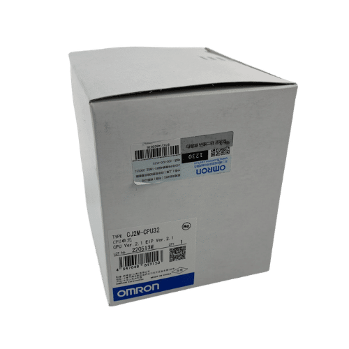
CPU Omron CJ2M-CPU32
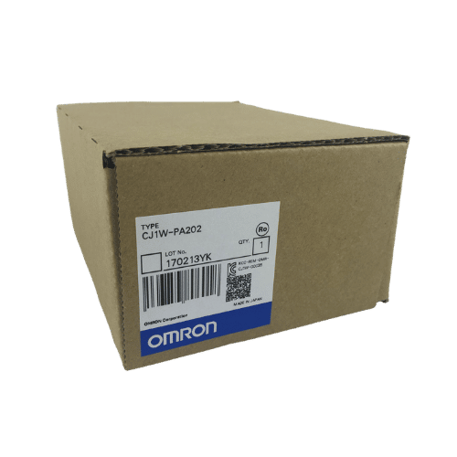
Furnizor Omron PLC CJ1W-PA202 din China
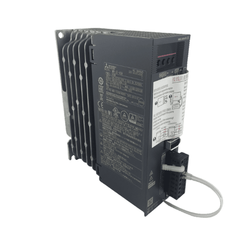
Servo Drive Mitsubishi MR-JE Seria 400w MR-JE-40A
Ai nevoie de o potrivire rapidă?
Împărtășește-ți modelul sau specificațiile, iar echipa noastră te va ajuta să găsești rapid potrivirea potrivită.
- Suport de specialitate
- Răspuns rapid
- Preț competitiv
- +86-755-81481609
- [email protected]
De asemenea, puteți găsi aceste subiecte interesante
Erori de comunicație EtherCAT la Omron NJ/NX după pornire: ghid de diagnosticare
Când controlerul Omron NJ/NX raportează erori EtherCAT după pornire, începeți cu primul eveniment relevant, adresa slave afectată și
Înțelegerea duratei ciclului PLC: optimizați-vă automatizarea
V-ați gândit vreodată cât de repede răspunde sistemul dumneavoastră de automatizare la schimbări? Secretul constă în timpul ciclului PLC-ului - pulsul sistemului dumneavoastră de control.
Senzorii fotoelectrici au nevoie de reflectoare? Perspective ale experților
O întrebare care apare frecvent este: Are nevoie un senzor fotoelectric de un reflector? Răspunsul nu este un simplu da sau nu - este...