Master Ladder Logic: Amit tudnod kell
- kwoco-plc.com
- 2024. október 13
- 8:21 du.
A Ladder Logic programozás egy programozási nyelv, amely a IEC 61131-3 szabvány, különféle automatizálási eszközök vezérlésére tervezték. Koncepciója egyértelmű: a bekötési áramkörökhöz hasonlóan bemeneti és kimeneti eszközöket is csatlakoztathat, és logikai feltételek alapján hajthat végre feladatokat.
- Egyszerűen fogalmazva, a Ladder Logic lehetővé teszi a gépek számára, hogy „gondolkodjanak” és hajtsanak végre feladatokat. Például, ha megnyomnak egy gombot, vagy egy érzékelő változást észlel, a PLC az előre megírt logikát követi olyan műveletek végrehajtásához, mint például a motor vagy szelep nyitása.
Merüljünk el, és nézzük meg, hogyan változtathatja a Ladder Logic PLC-jét mestervezérlővé!
Tartalomjegyzék
A Ladder Logic legfontosabb jellemzői
A Ladder Logic egy PLC programozási nyelv, amely követi a IEC 61131-3 szabvány, és széles körben használják az ipari automatizálásban. Ez a grafikus nyelv a hagyományos továbbítási logikát szimulálja, így a kódolási háttérrel nem rendelkező felhasználók számára könnyen érthető.
Főbb jellemzők
- IEC 61131-3 megfelelőség: A szabvány lefedi a Ladder Logic-ot és más PLC programozási nyelveket, mint például az utasításlista (IL) és a strukturált szöveg (ST), javítva a PLC-programozás következetességét.
- Működési elv: Az elektromos áramköröket utánozza a bemeneti eszközök (például gombok vagy gombok) összekapcsolásával érzékelők) kimeneti eszközökkel (például motorokkal vagy szelepekkel) egy logikai úton. A PLC szekvenciálisan vizsgálja a bemeneti állapotokat, és a logikai feltételek alapján indítja el a kimeneteket.
- Grafikus kifejezés: A Ladder Logic a kódot szimbólumokkal helyettesíti, lehetővé téve a felhasználók számára, hogy vezérlőlogikát építsenek fel vízszintes létrafokok függőleges síneken keresztüli összekapcsolásával, hasonlóan az áramköri diagramok olvasásához.
Ez a könnyen elsajátítható és intuitív felépítés a Ladder Logic-ot az egyik legnépszerűbb automatizálási nyelvvé teszi, amely ideális kezdők és a relérendszereket ismerők számára.
A létralogikai program kulcsfontosságú összetevői
Sínek és lépcsők
A sínek függőleges tápvezetékek, amelyek meghatározzák a bemeneti és kimeneti határokat. A létrafokok vízszintes összeköttetések a sínek között, utakat képezve, amelyek logikai műveleteken keresztül kapcsolják össze a bemeneteket és a kimeneteket.Bemenetek és kimenetek
A bemenetek, például a gombok vagy érzékelők jeleket küldenek a PLC-nek, és normál nyitott (NO) vagy normál zárt (NC) érintkezők képviselik őket. A kimenetek, mint például a motorok vagy lámpák, a bemeneti feltételek alapján aktiválódnak, és relé tekercsként jelölik.Logikai operátorok
A logikai szimbólumok, például az ÉS és a VAGY meghatározzák a bemenetek közötti kapcsolatot:- ÉS Logika: Csak akkor aktiválja a kimenetet, ha minden bemeneti feltétel teljesül.
- VAGY Logika: Aktiválja a kimenetet, ha bármelyik bemenet teljesül.
Időzítők és számlálók
- Időzítők: Késlelteti az eszközök aktiválását vagy deaktiválását.
- Számlálók: Kövesse nyomon a bemeneti események számát, támogatja a felfelé és lefelé történő számlálást.
Címke nevek és címek jelölése
Minden bemenethez és kimenethez tartozik egy memóriacím és egy címkenév, így a programozók könnyebben azonosíthatják és kezelhetik az eszközállapotokat.Megjegyzések és dokumentáció
A megjegyzések tisztázzák az egyes lépcsőfokok logikáját és működését, segítve a többi mérnököt a program megértésében és karbantartásában.
Ezek az elemek kombinálva robusztus vezérlőrendszereket hoznak létre, amelyek hatékony megoldásokat kínálnak az automatizálási projektekhez.
A létralogikai programozás alapvető elemei
Mik azok a sínek és lépcsők?
- Sínek: Jelképezi a tápvezetékeket, általában a bal oldalt a tápellátáshoz, a jobb oldalt pedig a semleges vagy földeléshez.
- Lépcsőfokok: A vezérlési logikát reprezentáló vízszintes utak, ahol a bemenetek és a kimenetek áramköröket alkotnak. A logika balról jobbra halad, és a kimenet aktiválódik, ha a feltételek teljesülnek.
Logikai kifejezések és feltételek
- ÉS Logika: A kimenet aktiválásához minden feltételnek igaznak kell lennie.
- VAGY Logika: Aktiválja a kimenetet, ha legalább egy feltétel teljesül.
Ezek a logikai kapcsolatok biztosítják az automatizált rendszerek zökkenőmentes működését, például a futószalag elindítását csak akkor, ha két érzékelő érzékeli a tárgyakat.
Gyakori buktatók a létralogikával kezdők számára, és hogyan lehet őket elkerülni
- Túlbonyolító logika: Legyen a program egyszerű és könnyen karbantartható.
- Elfelejti a programok mentését és feltöltését: Mindig ellenőrizze, hogy a változtatások fel lettek-e töltve a PLC-re.
- Az eszközcsatlakozások félreértése: Győződjön meg arról, hogy megértette az egyes bemenetek és kimenetek működését az áramkörön belül.
Miért érdemes létralogikát tanulni?
Az automatizálásban a Ladder Logic a PLC programozás „univerzális nyelve”. A gyártósorokon lévő robotkarok vezérlésétől a vízszivattyú-műveletek irányításáig terjedő feladatokra használják. A Mastering Ladder Logic lehetővé teszi, hogy pontos utasításokat adjon a gépeknek, és alkalmazkodjon a különféle automatizálási projektekhez.
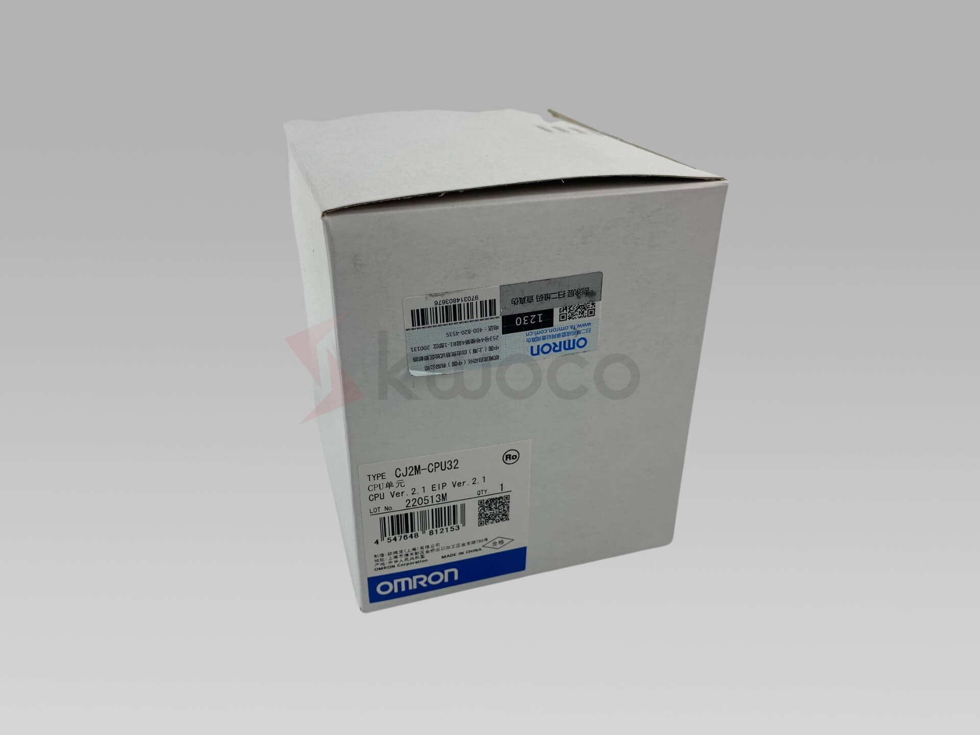
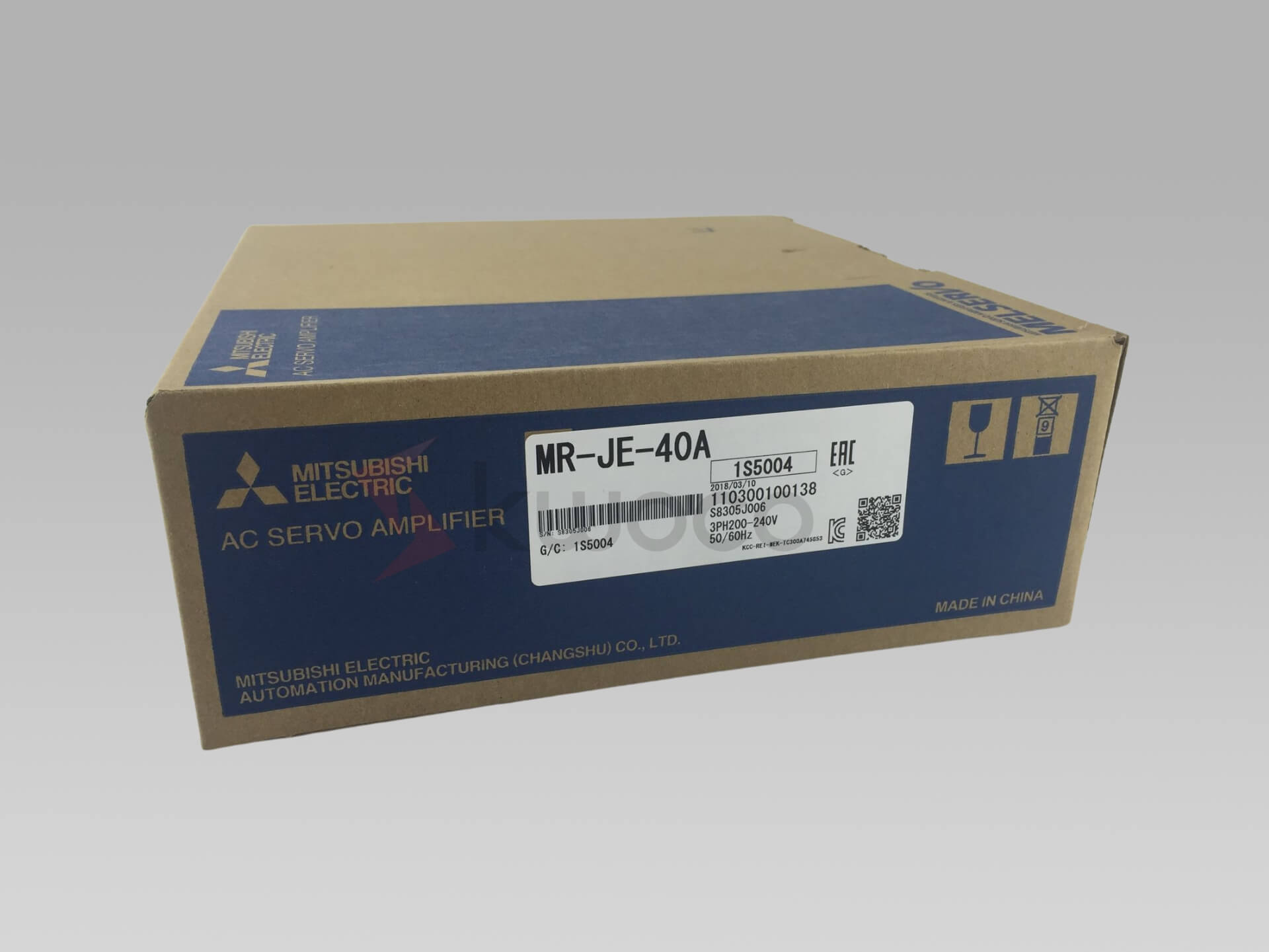
Ha azt tervezi, hogy dolgozni Omron vagy Mitsubishi PLC-k, a Ladder Logic elsajátítása elengedhetetlen.
Erősítse meg projektjeit vadonatúj, eredeti Omron, Mitsubishi, Schneider PLC segítségével – raktáron, készen áll!
Gyakran ismételt kérdések a létralogikáról
Mik a létralogikai programozás alapfogalmai?
A Ladder Logic egy grafikus nyelv, amelyet PLC-khez terveztek, és szimulálja a relévezérlő rendszereket a bemenetek és kimenetek létraszerű szerkezetben történő felhasználásával. Intuitív, még a korlátozott programozási ismeretekkel rendelkező felhasználók számára is.Mi a létralogika öt alapszabálya?
- Olvass balról jobbra, fentről lefelé.
- A bemenetek a bal oldalon, a kimenetek a jobb oldalon találhatók.
- A logika bináris állapotokon alapul (igaz/hamis, 1/0).
- Legyen egyszerű a logika a jobb karbantartás érdekében.
- A folyamatos szkennelés valós idejű választ biztosít.
Mik az alapvető utasítások a létralogikában?
- ÉS: Csak akkor aktiválja a kimenetet, ha minden feltétel igaz.
- VAGY: Aktiválja a kimenetet, ha bármely feltétel igaz.
- Időzítők: Késleltetett aktiválás vagy deaktiválás.
- Számlálók: A bemeneti események nyomon követése és kezelése.
- Beállítás/Visszaállítás: A kimeneti állapotok karbantartása vagy visszaállítása.
Melyek a létralogika alapvető műveletei?
- Beviteli állapot olvasása: A PLC átvizsgálja a bemeneteket, hogy rögzítse az állapotukat.
- Hajtsa végre a logikai ítéleteket: A bemeneteket a logika szerint értékeli.
- Kimeneti állapot frissítése: Logikai feltételek alapján aktiválja a kimeneteket.
- Ciklikus szkennelés: Folyamatosan ellenőrzi és végrehajtja az időben történő reagálást.
Ezek a műveletek alkotják a PLC-rendszerek magját, így az összetett automatizálási feladatok kezelhetők.
Következtetés
A létralogika elsajátítása nem nehéz, ha megérti alapelveit, és néhány egyszerű projekttel gyakorol. A raktáron lévő több mint 30 millió automatizálási termékkel, amelyek mindegyike új és eredeti, a Kwoco globális gyors szállítást kínál az Ön automatizálási igényeinek kielégítésére. Kérdései vannak? Nyugodtan írjon nekem e-mailt a következő címre: [email protected].
Lépjen kapcsolatba velünk
Csak töltse ki nevét, e-mail címét és kérésének rövid leírását ezen az űrlapon. 24 órán belül felvesszük Önnel a kapcsolatot.
Ezeket a témákat is érdekesnek találhatja

Navigálás a jövőben: Az ipari automatizálási ipar jelenlegi helyzetének feltárása
Az ipari automatizálási ipar soha nem látott ütemben fejlődik. Ez a cikk ennek a dinamikus szektornak a jelenlegi állapotát mutatja be, feltárja a fő trendeket, a piac méretét és a jövőbeli előrejelzéseket. Kötelező elolvasni, mert átfogó áttekintést ad arról, hol tart ma az iparág és merre tart, értékes betekintést nyújtva mindazok számára, akik érdeklődnek az ipari automatizálás iránt, vagy azzal foglalkoznak.

Relék: típusok és alkalmazások útmutatója
Ez a cikk alapos áttekintést nyújt a relékről, amelyek számos elektromos rendszer nem énekelt hősei. Megvizsgáljuk a relék különböző típusait, alkalmazásaikat és működésüket. Akár mérnök, akár technikus vagy egyszerűen csak kíváncsi a dolgok működésére, ez az átfogó útmutató megvilágítja a relék lenyűgöző világát.
Siemens meghajtó hibakód: Átfogó útmutató a hibaelhárításhoz és megoldáshoz
Ez a cikk részletes útmutatót nyújt a Siemens meghajtó hibakódjainak megértéséhez és hibaelhárításához. Akár tapasztalt mérnök, akár kezdő az ipari automatizálásban, ez az átfogó erőforrás segít gyorsan diagnosztizálni és megoldani a problémákat, minimalizálja az állásidőt és optimalizálja a termelékenységet. Érdemes elolvasni, mert gyakorlati betekintést, lépésről lépésre haladó instrukciókat és szakértői tanácsokat kínál a műveletek gördülékeny működéséhez.

